
Sheet press molding method and method of producing fuel cell separator

a technology of fuel cell separator and molding method, which is applied in the direction of sustainable manufacturing/processing, final product manufacturing, electrochemical generators, etc., can solve the problems of poor sheet molding ability, large thickness deviation of molded articles, poor molding ability of sheet materials, etc., to reduce the difference in the amount of compression deformation of sheet materials, reduce the difference in the amount of compression deformation, the effect of small thickness deviation

Inactive Publication Date: 2012-01-26
SHOWA DENKO KK
View PDF2 Cites 8 Cited by
  • Summary
  • Abstract
  • Description
  • Claims
  • Application Information

AI Technical Summary

Benefits of technology

The patent text describes a method for producing a fuel cell separator with improved power generation efficiency. The method involves using a sheet material containing a resin composition and a carbonaceous material as a filler. However, when the amount of filler is increased, the molded article becomes weaker and the thickness deviation becomes larger. The invention provides a sheet press molding method that can solve these problems. The method involves forming a recessed portion in the sheet material and then placing it in the dies to transfer the pattern for the fuel cell separator. The resulting fuel cell separator has small thickness deviation, high strength, and high electrical conductivity. The invention also includes a method of producing a fuel cell separator by applying pressure to a sheet material using a pair of dies, at least one of which has a recess-projection pattern.

Problems solved by technology

However, as the conventional sheet material containing a resin composition and filler such as a carbonaceous material, if the amount of filler is increased, the molding ability becomes poor when a molded article with a fine pattern is to be prepared.
In addition, there is another defect in that the thickness deviation of this molded article becomes larger.
However, as the fuel cell separator having a fine pattern of gas flow, when it is produced by molding a conventional sheet material containing a carbonaceous material and resin composition, as described above, not only sheet molding ability of the material becomes poor, but also there is another defect in that the thickness deviation of the separator becomes larger.
In addition, since the fuel cell separators are stacked to produce a fuel cell having a large number of units to achieve high power output, even a slight deviation of the individual thickness of the separator may cause a very large deviation in thickness of the fuel cell.
However, as the blending amount of a carbonaceous material contained in the sheet material increases, the strength of the resulting molded article obtained by press-molding sheet material is reduced.
Thus, even when using a conventional sheet material containing a carbonaceous material with a resin composition, a molded article can not be obtained with a sufficiently high strength and electrical conductivity as a fuel cell separator.

Method used


Image

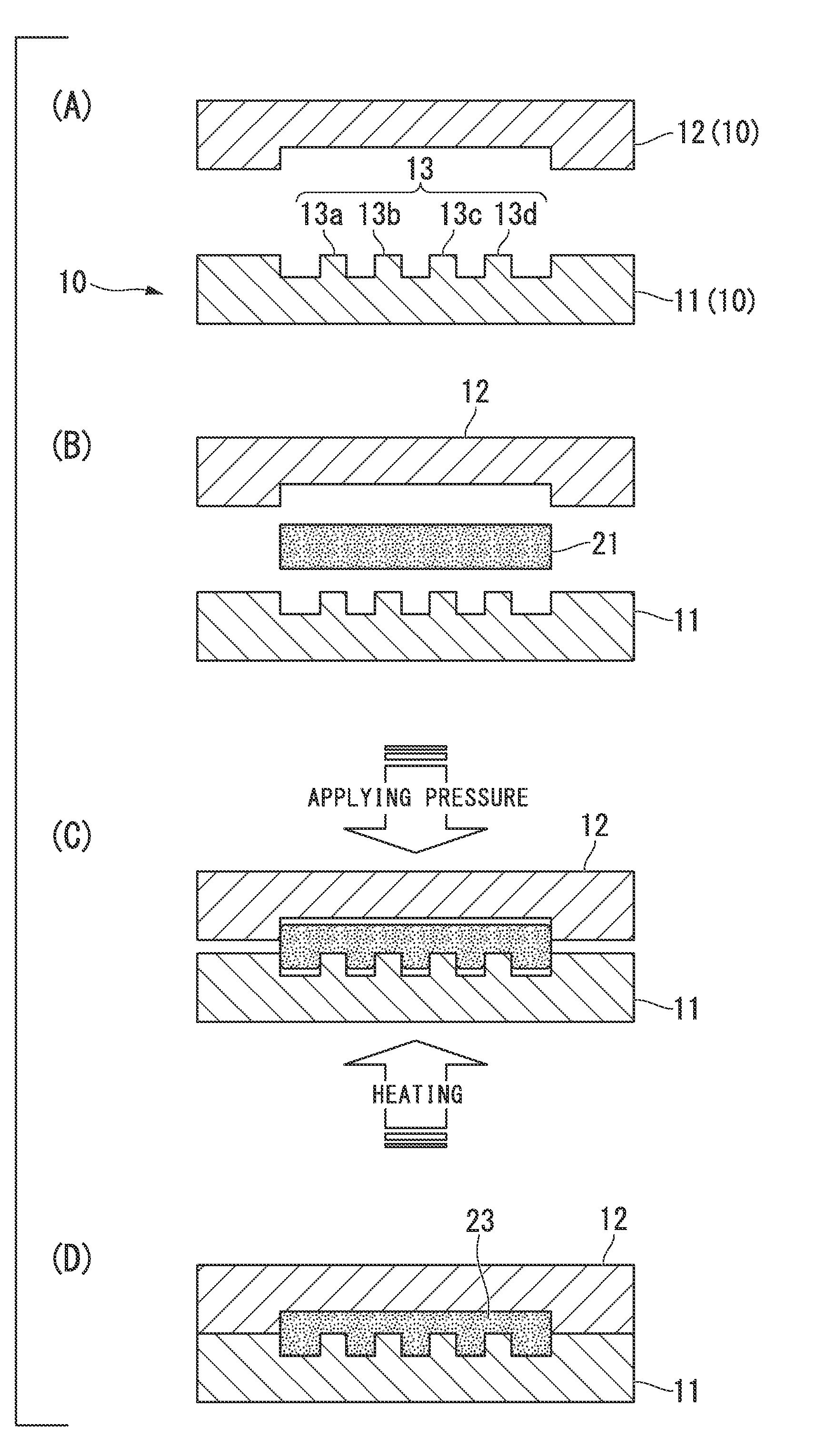
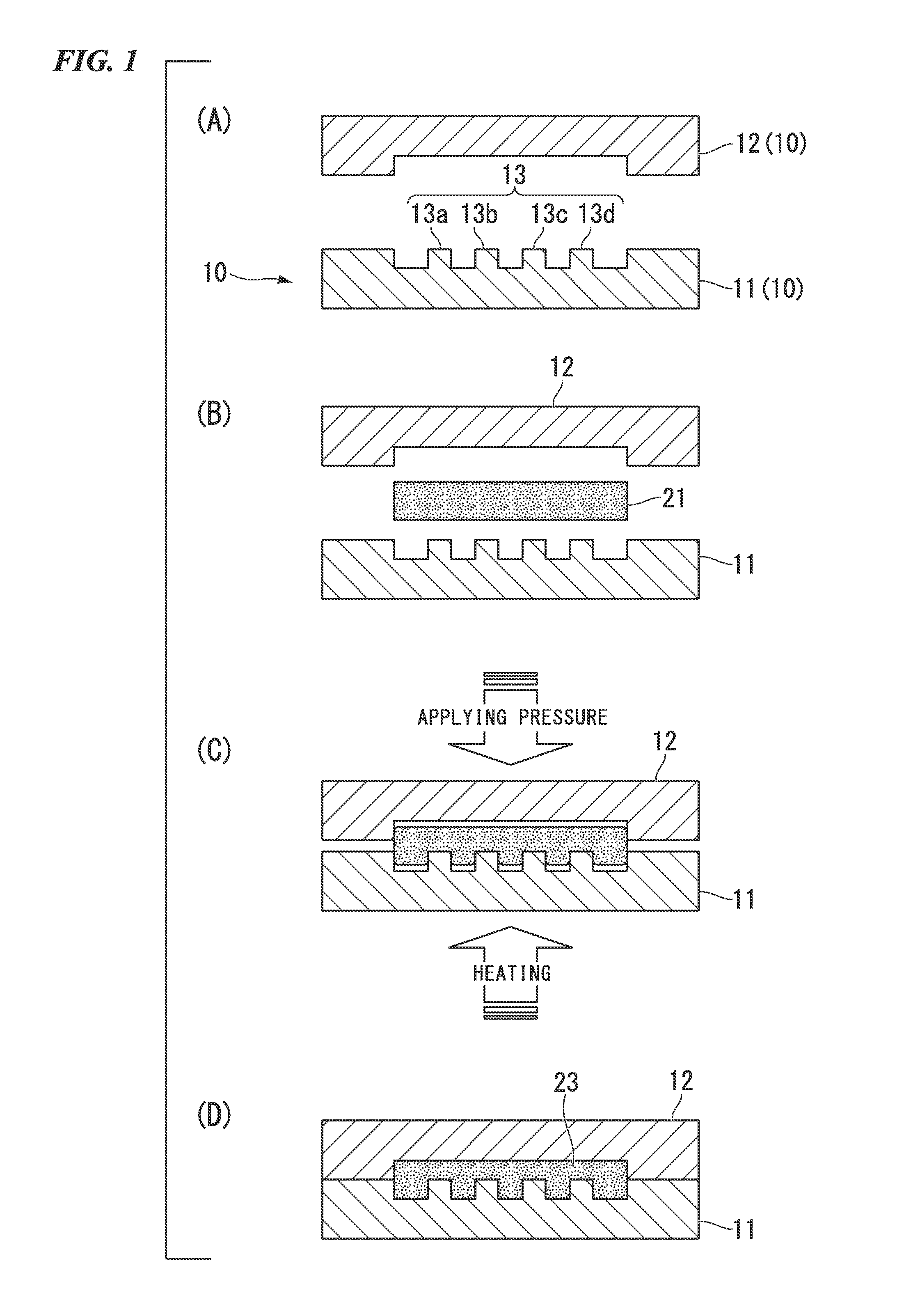
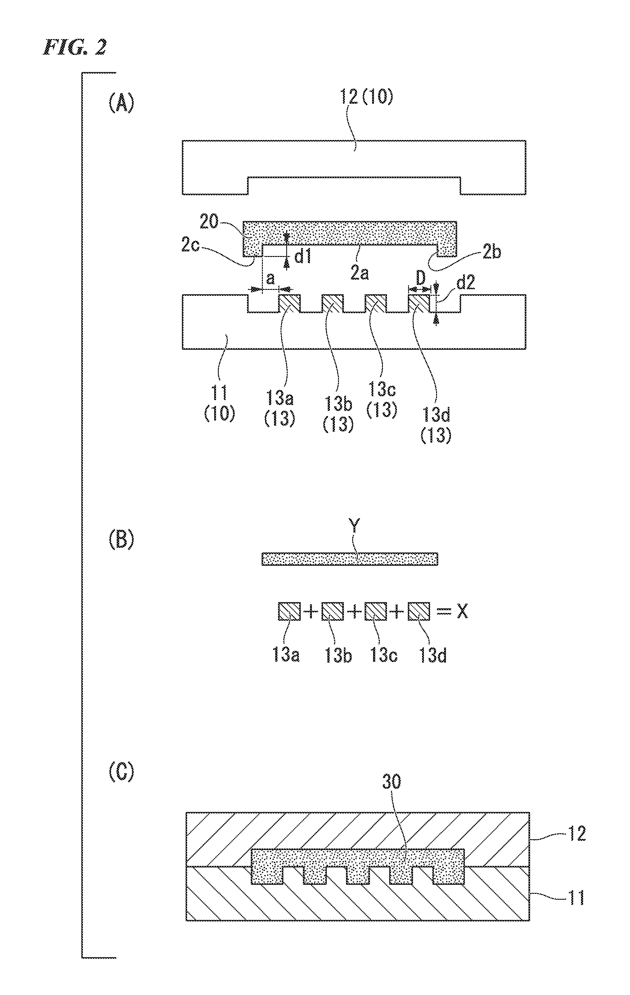
  • Sheet press molding method and method of producing fuel cell separator
  • Sheet press molding method and method of producing fuel cell separator
  • Sheet press molding method and method of producing fuel cell separator

Examples


example 1

[0163]A fuel cell separator of Example 1 as a molded article was produced by using the sheet press molding method of the present invention, using a sheet material containing a carbonaceous material as filler.

[0164]In other words, on the surface of the sheet material described below, a recessed portion was formed, as shown below (sheet-forming process); and then after the recessed portion of the sheet material was faced to the recess-projection pattern of the die shown below, under the following conditions of pressing process, the fuel cell separator 35, shown in FIG. 3, having the passage pattern 31 on one side which was transferred from the recess-projection pattern by applying pressure to the die, was obtained (pressing process). Further, in the pressing process, the recessed portion was placed to face the recess-projection pattern of the die by placing the edge of the recessed portion to the outer than the outermost projections among the recess-projection pattern of the die.

[0165...

example 2

[0196]A fuel cell separator of Example 2 was formed in the same manner as in Example 1, except that the recessed portion was formed by laminating a first sheet and a second sheet, wherein a portion of the first sheet corresponding to the recessed portion of the sheet material was eliminated through the first sheet, and the second sheet contained the same material as the first sheet.

[0197]As the first sheet, the sheet in which thickness was 0.32 mm and density was 1.6 g / cm3 was used. As the second sheet, the sheet in which thickness was 0.91 mm, density was 1.5 g / cm3 was used.

[0198]In addition, density of the fuel cell separator of Example 2 was 1.8 g / cm3.

[0199]The thickness deviation of the fuel cell separator obtained in Example 2 was evaluated in the same manner as in Example 1. The results were shown in FIG. 4(B) and Table 2. FIG. 4(B) is a graph showing the evaluation results of thickness deviation of the fuel cell separator of Example 2.


PUM

PropertyMeasurementUnit
thicknessaaaaaaaaaa
pressureaaaaaaaaaa
volumeaaaaaaaaaa

Abstract

Provided is a sheet press molding method that can create molded articles having low thickness deviation. In this method, a molded article (30) is formed by applying pressure to a sheet material (20) using a pair of dies (10), at least one of which has a prescribed recess-projection pattern (13) comprising recess and projection portions. The method includes: a sheet-forming process in which a recessed portion (2a) having volume equal to the total volume of the projection is formed in the surface of the sheet material (20), which includes a resin composite and 60-95% filler by volume; and a pressing process wherein the recessed portion (2a) in the sheet material (20) is placed facing the recess-projection pattern (13) on the dies (10) and pressure is applied to the dies (10), thereby forming a molded article (30) to which the recess-projection pattern (13) is transferred.

Description

TECHNICAL FIELD[0001]The present invention relates to a sheet press molding method and a method for producing a fuel cell separator. More particularly, the invention is related to a sheet press molding method using a sheet resin composition containing a high concentration filler, and a method for producing a fuel cell separator using a resin composition sheet containing a high concentration of carbonaceous material.[0002]Priority is claimed on Japanese Patent Application No. 2009-082619, filed Mar. 30, 2009, the content of which is incorporated herein by reference.BACKGROUND ART[0003]In recent years, as a molding method for thin products having a large area, a sheet press molding method has been focused on. This method has been used for molding fuel cell separators. Below, an example method for producing a fuel cell separator is used to describe a sheet press molding method.[0004]Fuel cells generate electricity by the reverse reaction of electrolysis of water using hydrogen and oxyg...

Claims


Application Information

Patent Timeline
Patent Type & Authority Applications(United States)
IPC IPC(8): B29C43/02
CPCB29C33/42B29C43/003B29C43/021B29C43/36B29C2043/023Y02E60/50B29K2709/08H01M8/0213H01M8/0221H01M8/0226B29C2043/025B29L2031/3468B29C43/14Y02P70/50B29C43/02B29C59/02H01M8/02
Inventor UTASHIRO, TOMOYAITO, YOSHINORINOGUCHI, MASAYUKI
Owner SHOWA DENKO KK
Learn More