
Steel plate manufacturing facility and manufacturing method

Inactive Publication Date: 2012-01-26
JFE STEEL CORP
View PDF5 Cites 12 Cited by
  • Summary
  • Abstract
  • Description
  • Claims
  • Application Information

AI Technical Summary

Benefits of technology

[0013]Furthermore, since the descaler removes scale produced on each surface of the steel plate after hot leveling of the steel plate by the hot leveler, spraying nozzles of the descaler can be moved closer to the surfaces of the hot-leveled steel plate, thereby improving the descaling performance. Alternatively, the cooling water spraying performance of the descaler for providing a predetermined pressure at the point of impact can be set to low.
[0015]In the steel plate manufacturing facility, preferably, the components are arranged such that the distance L between the descaler and the cooling equipment is less than or equal to 12 m. According to embodiments of the invention, cooling of the steel plate by the cooling equipment is very stable.
[0016]In the steel plate manufacturing facility, preferably, the distance H between each spraying nozzle of the descaler and the surface of the steel plate is greater than or equal to 40 mm and less than or equal to 140 mm. According to embodiments of the invention, the spraying pressure and spray flow rate of the descaler for providing a predetermined pressure at the point of impact are low, thus reducing the pump capacity of the descaler.
[0018]According to exemplary embodiments of the invention, cooling water supplied from the cooling water spraying nozzles through the water supply inlets cools the upper surface of the steel plate to turn to high-temperature drainage water and the drainage water flows from the drain outlets onto the dividing plate so that the drainage water after cooling is immediately eliminated from the steel plate. Advantageously, the cooling equipment offers adequate cooling performance that is uniform in the width direction.
[0021]In the steel plate manufacturing method, preferably, when T [K] denotes the temperature of the steel plate before cooling, the period of time t [s] between the completion of the descaling step and the start of the cooling step satisfies the expression t≦5×10⁻⁹×exp(25000 / T). According to exemplary embodiments of the invention, cooling of the steel plate in the cooling step can be stabilized.
[0022]According to the steel plate manufacturing facility and manufacturing method of exemplary embodiments of the present invention, uniform descaling can be performed in the descaling step and uniform cooling can be achieved in the cooling step, so that the steel plate excellent in steel plate shape and mechanical property can be manufactured.

Problems solved by technology

In actually manufacturing a steel plate using the methods disclosed in Patent Literature 1 and Patent Literature 2 mentioned above, in some cases, scale is not completely removed during descaling, but descaling causes scale nonuniformity, resulting in poor surface condition.
The pressures at the point of impact of cooling water are low and the disclosed methods do not offer the performance of achieving uniform descaling.
Disadvantageously, uniform cooling is not achieved during controlled cooling.
The harmful effect of cooling rate nonuniformity caused by the above-described scale nonuniformity during controlled cooling on material uniformity, especially in the width direction of the steel plate, is becoming unignorable.

Method used


Image

  • Steel plate manufacturing facility and manufacturing method
  • Steel plate manufacturing facility and manufacturing method
  • Steel plate manufacturing facility and manufacturing method

Examples


examples

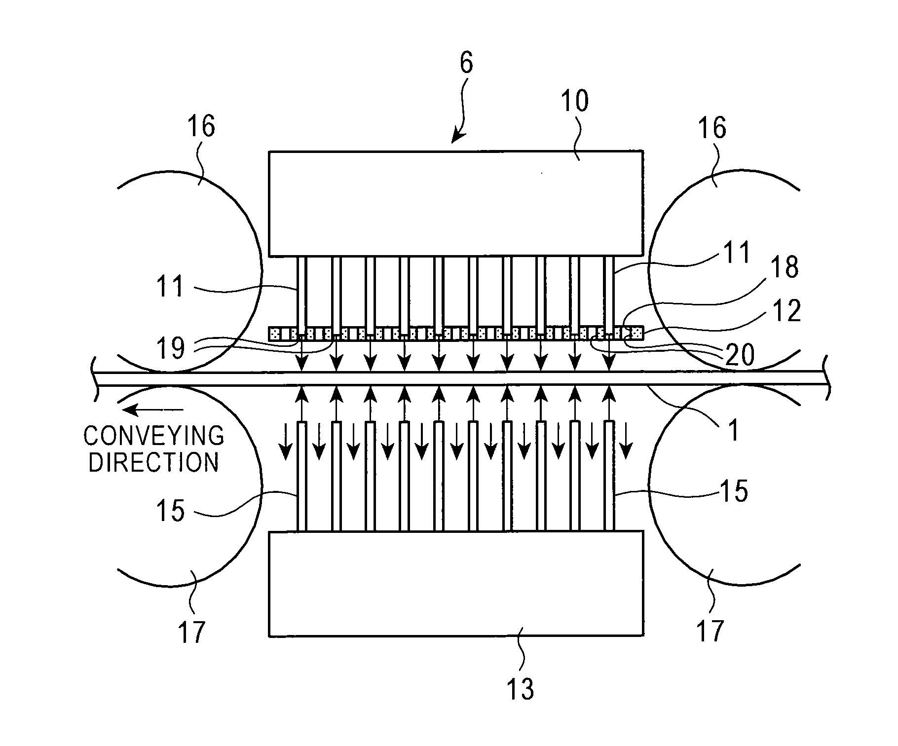
[0082]The steel plate 1, rolled by the hot rolling mill 3, having a thickness of 30 mm and a width of 3500 mm was passed through the first hot leveler 5 and the descaler 4 and was then controlled such that the steel plate was cooled from 820° C. to 420° C. As regards a condition for stable cooling calculated from the above-described expressions (6), (7), and (8), the period of time t between the completion of removal of scale on the steel plate 1 by the descaler 4 and the start of cooling of the steel plate 1 by the cooling equipment 6 is less than or equal to 42 s, preferably, less than or equal to 19 s, and more preferably, less than or equal to 5 s.

[0083]As regards the descaler 4, the spraying pressure of nozzles was 17.7 MPa, the spray flow rate per nozzle was 64 L / min / nozzle, the spraying distance (the distance between each spraying nozzle of the descaler 4 and each surface of the steel plate 1) was 130 mm, the spray angle of nozzle was 32°, the angle between the spray directio...


PUM

PropertyMeasurementUnit
Pressureaaaaaaaaaa
Distanceaaaaaaaaaa
Distanceaaaaaaaaaa

Abstract

A facility is provided for manufacturing a steel plate excellent in steel plate shape and mechanical property while setting low cooling-water spraying performance in a descaling step and achieving uniform cooling in a cooling step. Specifically, a hot rolling mill 3, a first hot leveler 5, a descaler 4, and cooling equipment 6 are arranged in that order from the upstream side in a conveying direction. A pressure P [MPa] at the point of impact of cooling water sprayed from the descaler to each surface of a steel plate 1 is greater than or equal to 1.5 MPa.

Description

CROSS-REFERENCE TO RELATED APPLICATIONS[0001]This application is the U.S. National Phase application of PCT International Application No. PCT / JP2010 / 055497, filed Mar. 23, 2010, and claims priority to Japanese Patent Application No. 2009-073994, filed Mar. 25, 2009, and Japanese Patent Application No. 2010-006722, filed Jan. 15, 2010, the disclosures of which PCT and priority applications are incorporated herein by reference in their entirely for all purposes.FIELD OF THE INVENTION[0002]The present invention relates to a steel plate manufacturing facility and manufacturing method of hot rolling, hot leveling, and cooling a steel plate.BACKGROUND OF THE INVENTION[0003]The application of cooling control as a process of manufacturing a steel plate has recently been widening. Since a typical hot rolled steel plate is not necessarily uniform in, for example, shape and surface condition, however, strip temperature deviation tends to occur in the steel plate during cooling. The occurrence ...

Claims


Application Information

Patent Timeline
IPC IPC(8): B21B45/04B21B45/02
CPCB21B39/08B21B45/08B21B45/0218B21B45/02B21B39/00
Inventor KUROKI, TAKASHINAKATA, NAOKIHIRATA, KENJIFURUMAI, TAKAYUKIFUJII, YUKIOTERASAKI, MOTOJI
Owner JFE STEEL CORP
Learn More