Touch panel

a touch panel and touch technology, applied in the field of touch panels, can solve the problems of insatiable inability to effectively reduce the difference between the transmission impedances of different signal transmission paths, and user's inability to operate the touch panel with gloves on or using a non-conductive material, etc., to achieve the effect of improving the signal transmission quality of the touch panel, reducing the difference between the transmission impedances of different signal transmission paths, and not significantly varied signal transmission lines

Inactive Publication Date: 2012-01-12
DONGGUAN MASSTOP LIQUID CRYSTAL DISPLAY +1
View PDF21 Cites 9 Cited by
  • Summary
  • Abstract
  • Description
  • Claims
  • Application Information

AI Technical Summary

Benefits of technology

[0007]Accordingly, the invention is directed to a touch panel, wherein the transmission impedance difference of a plurality of signal transmission paths is reduced and the transmission quality of the touch signal is improved.
[0009]As described above, in the invention, the distance from two opposite ends of each conductive pattern to a corresponding connection region is not greater than the distances from the two opposite ends of the conductive pattern to other connection regions. Thus, in the invention, the transmission distances of the signal transmission lines are not significantly varied. Thereby, the difference among transmission impedances of different signal transmission paths is effectively reduced and accordingly the signal transmission quality of the touch panel is improved.

Problems solved by technology

However, because the capacitive touch panel has to be operated by using a conductive material, a user cannot operate it with gloves on or by using a non-conductive material.
Thus, in the conventional technique, the difference between the transmission impedances cannot be effectively reduced, and accordingly the signal transmission quality of the touch panel is not satisfactory.
Besides, the impedance ratio between the touch sensing region and the transmission line region of the touch panel cannot provide 20:1 ratio to satisfy the chip specification.

Method used


Image

  • Touch panel
  • Touch panel
  • Touch panel

Examples


Embodiment Construction

[0018]Reference will now be made in detail to the present preferred embodiments of the invention, examples of which are illustrated in the accompanying drawings. Wherever possible, the same reference numbers are used in the drawings and the description to refer to the same or like parts.

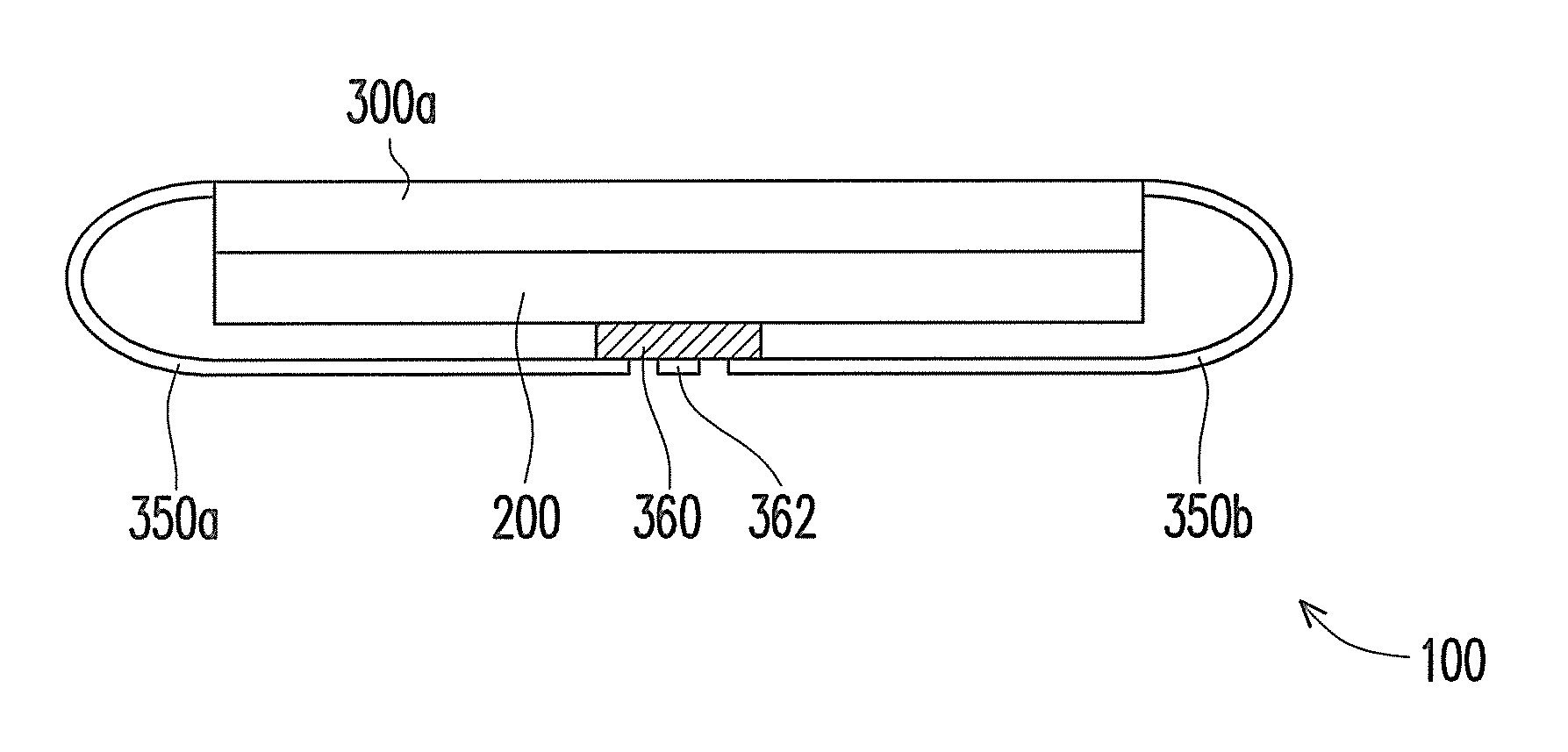
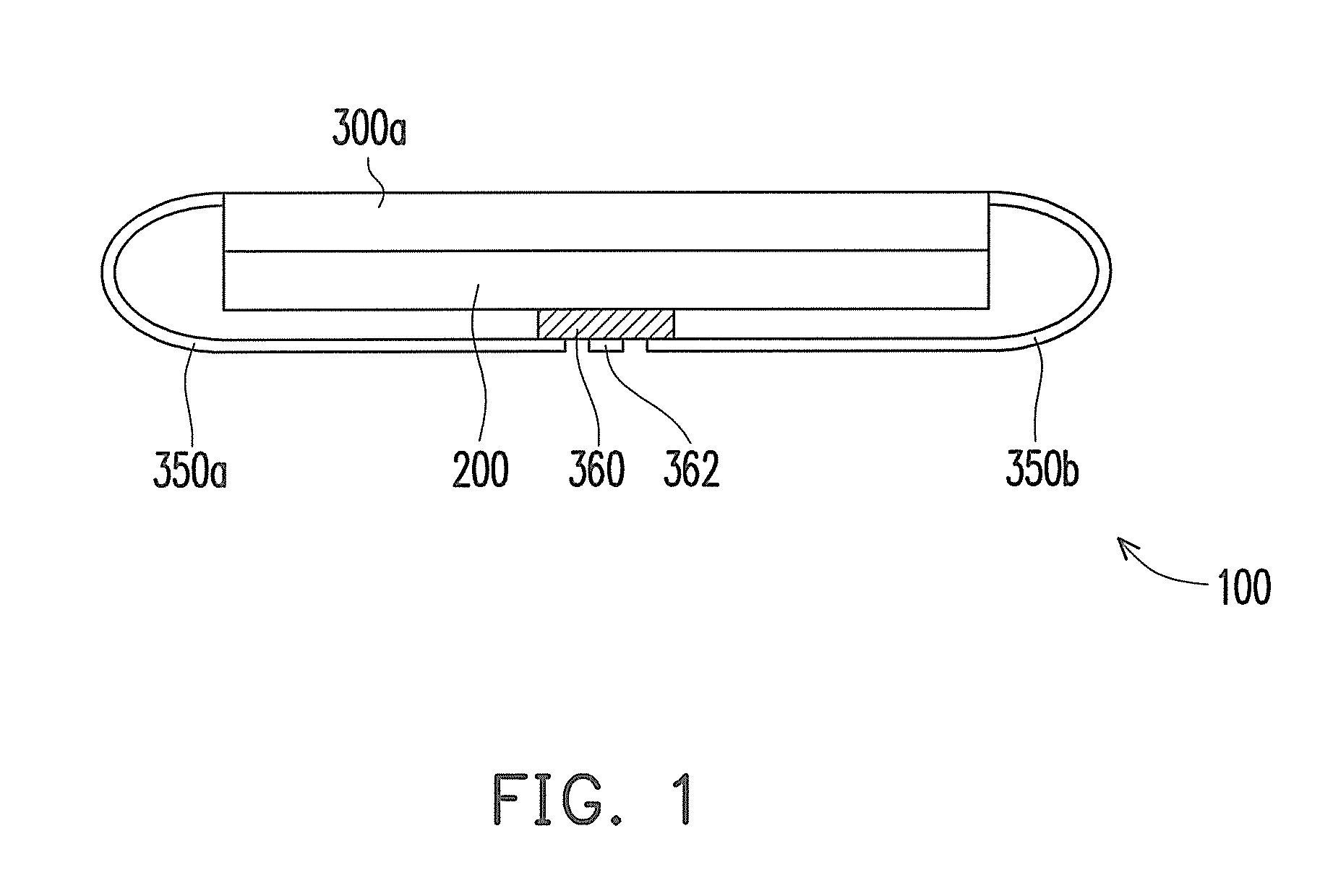
[0019]FIG. 1 is a diagram of a touch display device according to an embodiment of the invention. FIG. 2A is a top view of a touch panel of the touch display device in FIG. 1. FIG. 2B is a bottom view of the touch panel in FIG. 2A. Referring to FIG. 1, in the present embodiment, the touch display device 100 includes a display panel 200 and a touch panel 300a. The display panel 200 is disposed below the touch panel 300a, and can be a liquid crystal display (LCD) panel, an organic electro-luminescence display panel, a plasma display panel, an electronic paper panel, an electro wetting display panel, or other types of flat display panels. However, the invention is not limited thereto.

[0020]Referring to F...


PUM


Abstract

A touch panel having a touch sensing region and at least two connection regions around the touch sensing region is provided. The touch panel includes first conductive patterns, second conductive patterns, pads, and signal transmission lines. The first and second conductive patterns are disposed in the touch sensing region. Each first conductive pattern has a first end and an opposite second end. Each second conductive pattern has a third end and an opposite fourth end. The pads are respectively disposed in the connection regions. The first, second, third, and fourth ends are electrically connected to the pads in the corresponding connection region respectively through the signal transmission lines so that the distance from each first end, each second end, each third end, and each fourth end to the corresponding connection region is not greater than the distance from those to the other connection region.

Description

CROSS-REFERENCE TO RELATED APPLICATION[0001]This application claims the priority benefit of Taiwan application serial no. 99122682, filed Jul. 9, 2010. The entirety of the above-mentioned patent application is hereby incorporated by reference herein and made a part of this specification.BACKGROUND OF THE INVENTION[0002]1. Field of the Invention[0003]The invention generally relates to a touch panel, and more particularly, to a touch panel having improved signal transmission quality.[0004]2. Description of Related Art[0005]Existing touch panels can be generally categorized into resistive touch panels, capacitive touch panels, infrared touch panels, and ultrasonic touch panels, wherein the resistive touch panels and the capacitive touch panels are presently the most popular products. The feature of multi-point touch control in a capacitive touch panel allows the capacitive touch panel to provide a more intuitional operation mode. Accordingly, the capacitive touch panel has been focused...

Claims


Application Information

Patent Timeline
Patent Type & Authority Applications(United States)
IPC IPC(8): G06F3/041
CPCG06F3/045G06F3/044G06F3/0446G06F3/04164
Inventor LIAO, HSIAO-HUILAI, CHIH-CHANGHO, KUN-CHANG
Owner DONGGUAN MASSTOP LIQUID CRYSTAL DISPLAY
Why Eureka
Try Eureka