
Semiconductor device and semiconductor device manufacturing method

Inactive Publication Date: 2012-01-05
TOKYO ELECTRON LTD
View PDF3 Cites 1 Cited by
  • Summary
  • Abstract
  • Description
  • Claims
  • Application Information

AI Technical Summary

Benefits of technology

[0010]In view of the foregoing, the present disclosure provides a semiconductor device and a semiconductor device manufacturing method capable of preventing electrical leakage while suppressing increase of wiring resistance and deterioration of productivity.
[0013]In accordance with the present disclosure, it is possible to provide a semiconductor device and a semiconductor device manufacturing method capable of preventing electrical leakage while suppressing increase of wiring resistance and deterioration of productivity.

Problems solved by technology

If a trench or a hole is formed in such a porous low-k film by plasma etching or the like, an inner wall of the trench or the hole exposed to plasma may be damaged and deteriorated.
Furthermore, if the pores are not separated but connected as a continuous hole, a wiring metal may be diffused even to the inside of the low-k film through the continuous hole, resulting in electrical leakage.
As a result, the metal may diffuse within the pores, raising a likelihood of generation of electrical leakage.
Further, roughness of the inner sidewall may be increased, resulting in increase of wiring resistance as well.
These problems may become remarkable when the dielectric constant of the low-k film is further reduced by increasing the porosity of the low-k film.
Thus, a sealing layer removing process for removing this sealing layer on the copper wiring needs to be performed, which may result in deterioration of productivity due to increase of the number of required processes.

Method used


Image

  • Semiconductor device and semiconductor device manufacturing method
  • Semiconductor device and semiconductor device manufacturing method
  • Semiconductor device and semiconductor device manufacturing method

Examples


Embodiment Construction

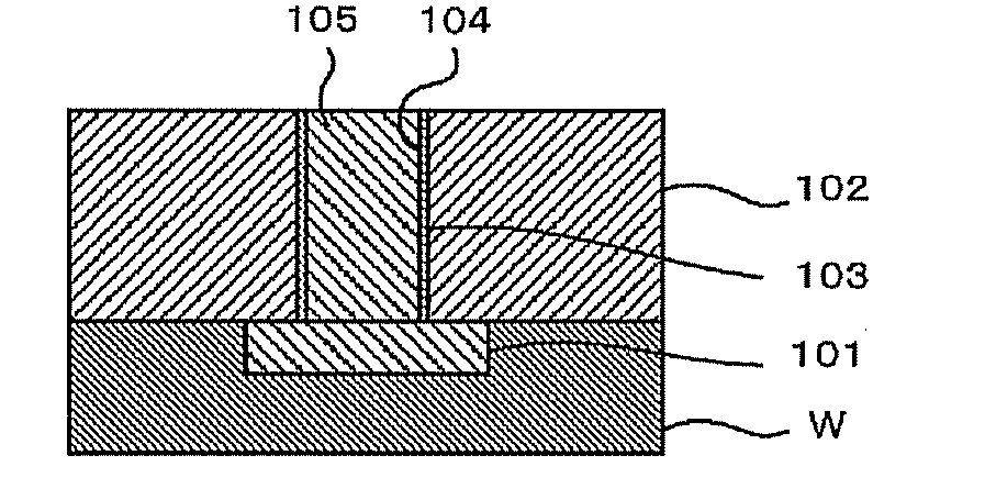
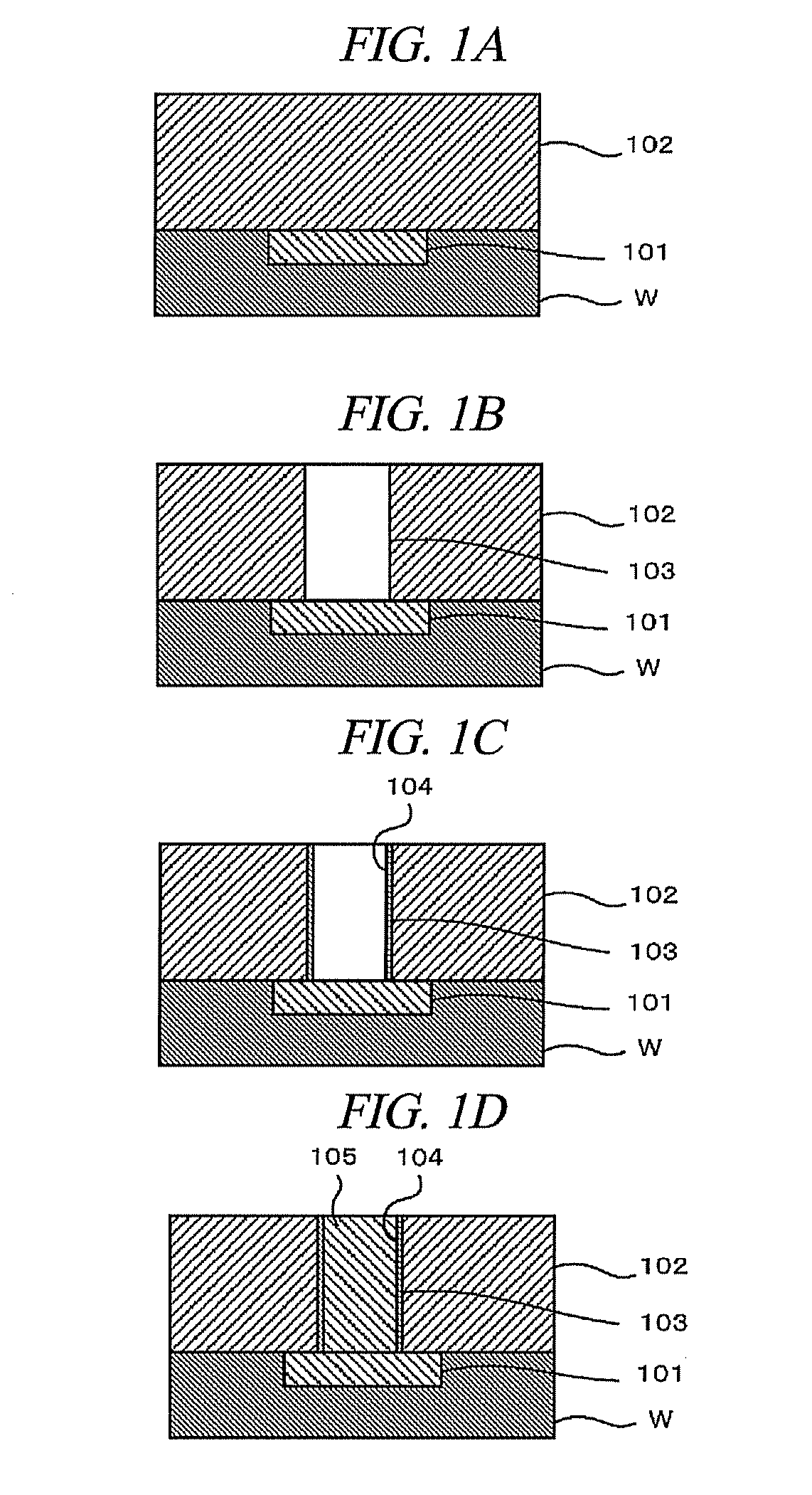
[0020]Hereinafter, embodiments of the present disclosure will be described in detail with reference to the accompanying drawings. FIGS. 1A to 1D depict cross sectional views schematically showing a structure of major parts of a semiconductor wafer W in order to describe a semiconductor device manufacturing method in accordance with an embodiment of the present disclosure. In the present embodiment, as depicted in FIGS. 1A to 1D, a porous low-k film 102 is formed on a semiconductor wafer W having an underlying copper wiring 101 or the like (FIG. 1A).

[0021]By way of example, Black Diamond (Registered Trademark: Applied Materials Corp.) or Aurora (Registered Trademark: ASM International N.V.) may be used as the porous low-k film 102.

[0022]Subsequently, a trench (or hole) 103 is formed at a certain portion of the porous low-k film 102 such that a part of the underlying copper wiring 101 is exposed (FIG. 1B). This process may be implemented by, e.g., plasma etching using a patterned phot...


PUM


Abstract

There are provided a semiconductor device and a semiconductor device manufacturing method capable of preventing electrical leakage while suppressing increase of wiring resistance and deterioration of productivity. The semiconductor device manufacturing method for forming on a substrate a semiconductor device having a porous low-k film serving as an interlayer insulating film. Further, the semiconductor device manufacturing method includes forming the low-k film on the substrate; etching the low-k film to form a trench or a hole therein; reforming a surface of the low-k film exposed by etching the low-k film by allowing plasma of a nitro compound to act on the exposed surface within the trench or the hole; and filling the trench or the hole with a conductor.

Description

CROSS-REFERENCE TO RELATED APPLICATION[0001]This application claims the benefit of Japanese Patent Application No. 2010-152217 filed on Jul. 2, 2010, the entire disclosures of which are incorporated herein by reference.FIELD OF THE INVENTION[0002]The present disclosure relates to a semiconductor device and a semiconductor device manufacturing method.BACKGROUND OF THE INVENTION[0003]Conventionally, in the field of manufacture of a semiconductor device, a low-k film such as a SiCHO-based film has been used as an insulating layer, e.g., an interlayer insulating film. It has been considered to further reduce a dielectric constant of such a SiCHO-based low-k film by forming pores in the low-k film, i.e., forming a porous low-k film and increasing the porosity thereof.[0004]If a trench or a hole is formed in such a porous low-k film by plasma etching or the like, an inner wall of the trench or the hole exposed to plasma may be damaged and deteriorated. As a solution, there has been known ...

Claims


Application Information

Patent Timeline
IPC IPC(8): H01L23/48H01L21/768
CPCH01L21/3105H01L21/76831H01L21/76826H01L21/76814H01L21/28H01L21/3205
Inventor ASAKO, RYUICHI
Owner TOKYO ELECTRON LTD
Learn More