
Multifilament Superconductor Having Reduced AC Losses and Method for Forming the Same

Active Publication Date: 2011-12-29
SUPERPOWER INC +1
View PDF4 Cites 35 Cited by
  • Summary
  • Abstract
  • Description
  • Claims
  • Application Information

AI Technical Summary

Benefits of technology

[0015]According to a first aspect of the present disclosure, a high temperature superconductor structure is provided comprising a substrate on which at least one buffer layer is deposited, said substrate having a length and a width, wherein the length is at least about 100 m and the substrate has a dimension ratio of not less than about 103; a superconductor layer on said at least one buffer layer, said layer comprised of superconductor material that forms at least two substantially parallel superconductor filaments that continuously extend along the length of said substrate; wherein the at least two superconductor filaments are separated from each other by at least one insulating strip having a first and second surface opposite each other, said first surface overlying said buffer layer and said second surface being substantially free of said superconductor material; wherein the at least one insulating strip continuously extends along the length of said substrate and is comprised of insulating material with a resistivity greater than abo

Problems solved by technology

The drawbacks of 1G wires are the high materials costs (e.g. Ag), elaborate processing operations, and generally poor critical current performance in high magnetic fields at high temperatures, which limit the lengths of the wires.
Recent prototypes have confirmed the great potential of HTS wire in electric power applications but have also shed light on deficiencies that pose risk to their widespread implementation.
Although superconductors have zero resistance to DC current, the architecture of the coated conductor has yet to be optimized for AC applications, such as motors, generators, and transformers.
In particular, the width to thickness ratio of HTS wire is high, which results in HTS coated conductors exhibiting very high hysteretic losses.
In practice, AC losses result in increased cryogenic burden and impose risks on electric power systems.
To mitigate these risks, higher cooling capacities or redundant cooling equipment must be used, which greatly increases the overall system cost and is a significant deterrent to the adoption of this immature technology.
Although these multifilament conductors have been shown to greatly reduce hysteretic losses, numerous engineering and manufacturing challenges remain prior to full commercialization of these HTS wires because the scale up of multifilamentary 2G HTS wire to industrial manufacturing is fraught with numerous barriers.
The use of an etchant inevitably results in damage to the superconducting material, such as edge rippling, undercutting, and broken filaments.
More specifically, the filament damage greatly reduces the current carrying capacity of the HTS wire.
Furthermore, if the etching process is modified to avoid filament damage, bridges or other incomplete separations between the filaments may be left behind which results in the coupling of filaments and negates the AC loss reduction.
In fact any superconductor residue that remains in the gaps after etching can result in filamentary coupling.
If the gap is widened to circumvent these problems, more superconducting material is removed which greatly reduces the current carrying capacity of the wire.
As such, producing kilometer-long 2G HTS wires with fine filaments of continuous superconducting parallel lines, running end to end poses a technological barrier to scaling up the use of HTS wire in electric power systems.
As such, a commercially feasible method does not exist for fabricating an AC tolerant HTS wire by an etch-free process to produce a multi-filament HTS layers.
However, these techniques result in unintentional coupling of filaments that leads to poor and inconsistent AC loss reduction and tapes that cannot be utilized even in meter lengths, yet alone kilometer lengths.

Method used


Image

  • Multifilament Superconductor Having Reduced AC Losses and Method for Forming the Same
  • Multifilament Superconductor Having Reduced AC Losses and Method for Forming the Same
  • Multifilament Superconductor Having Reduced AC Losses and Method for Forming the Same

Examples


Embodiment Construction

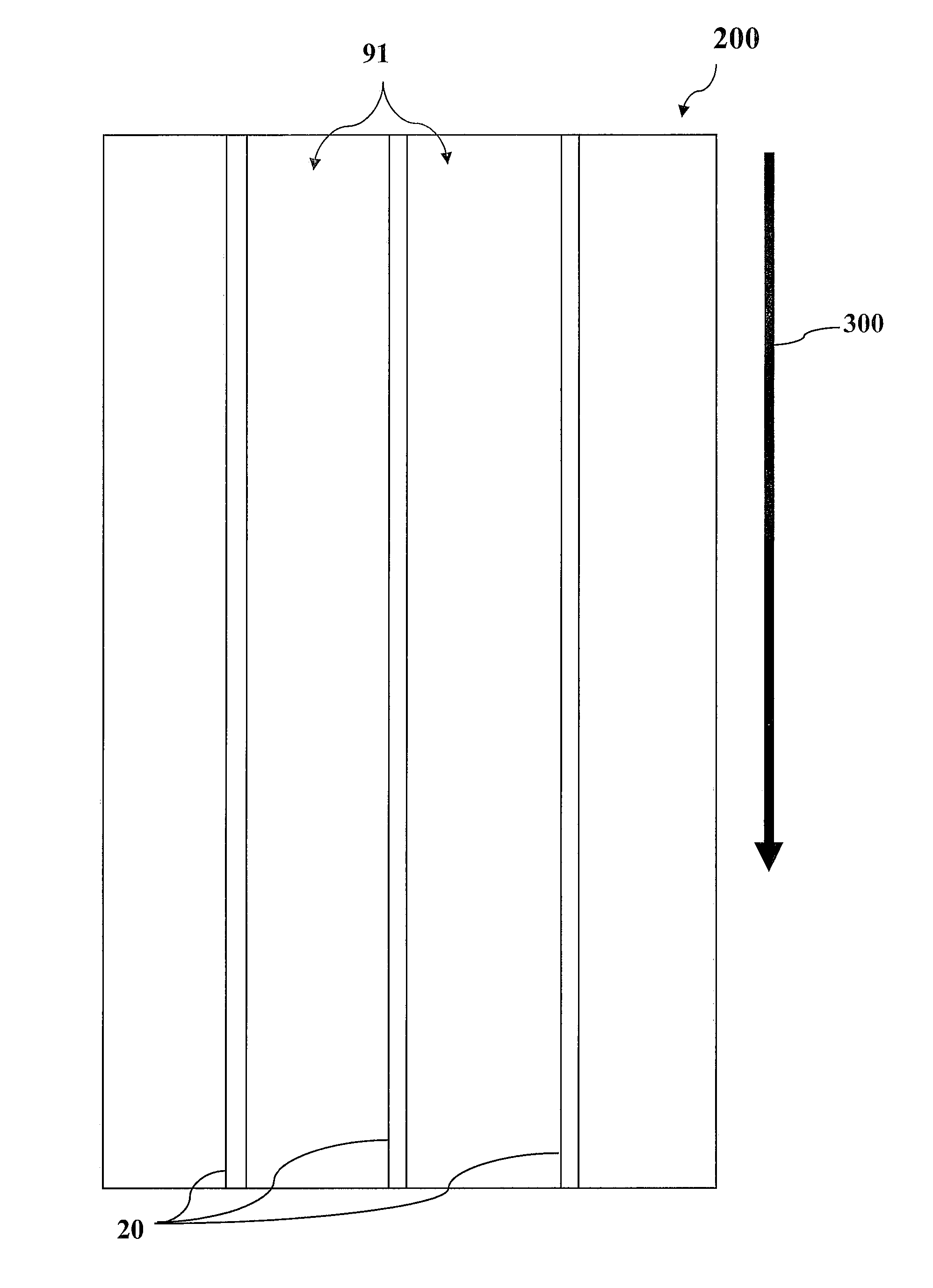
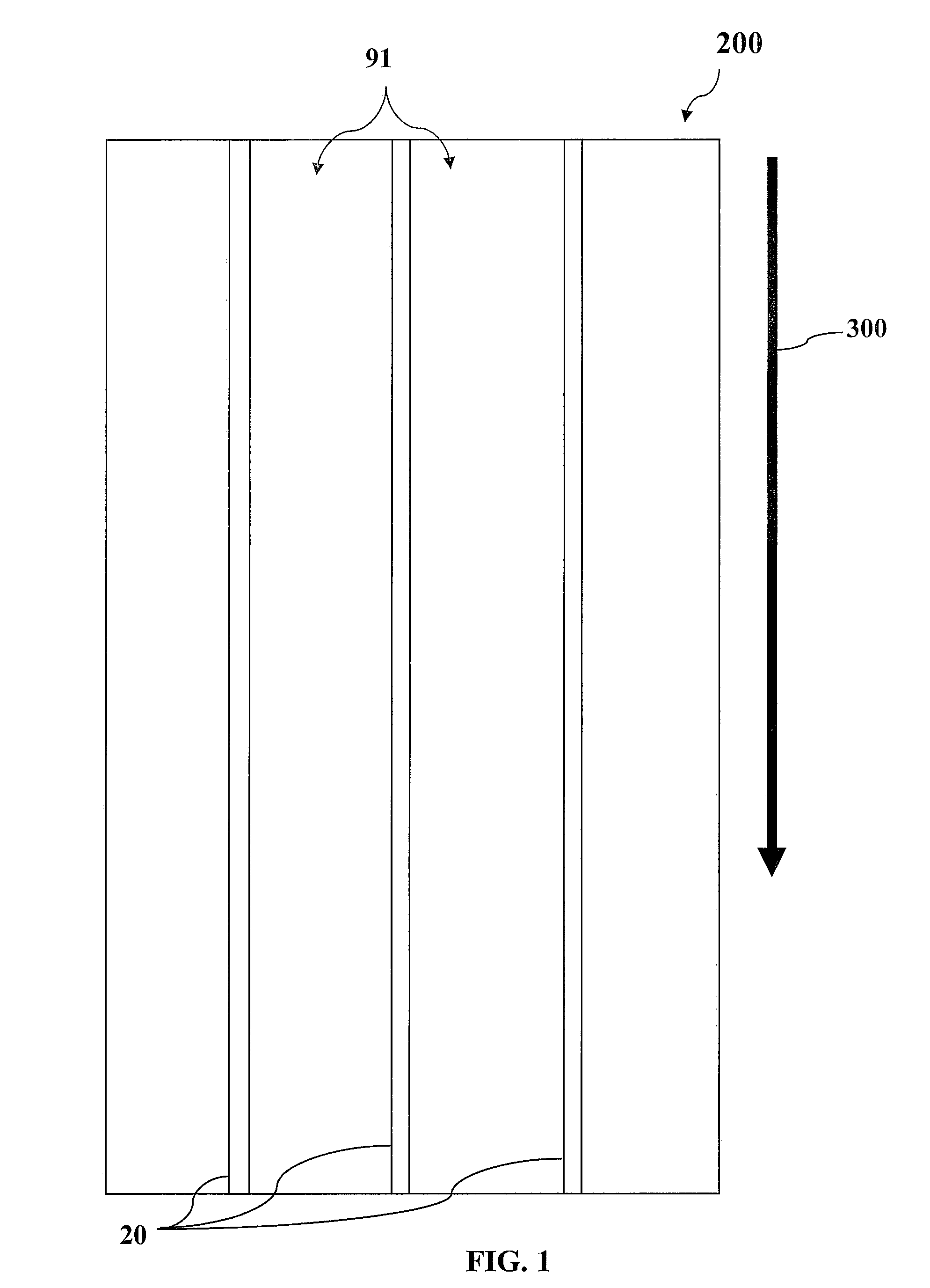
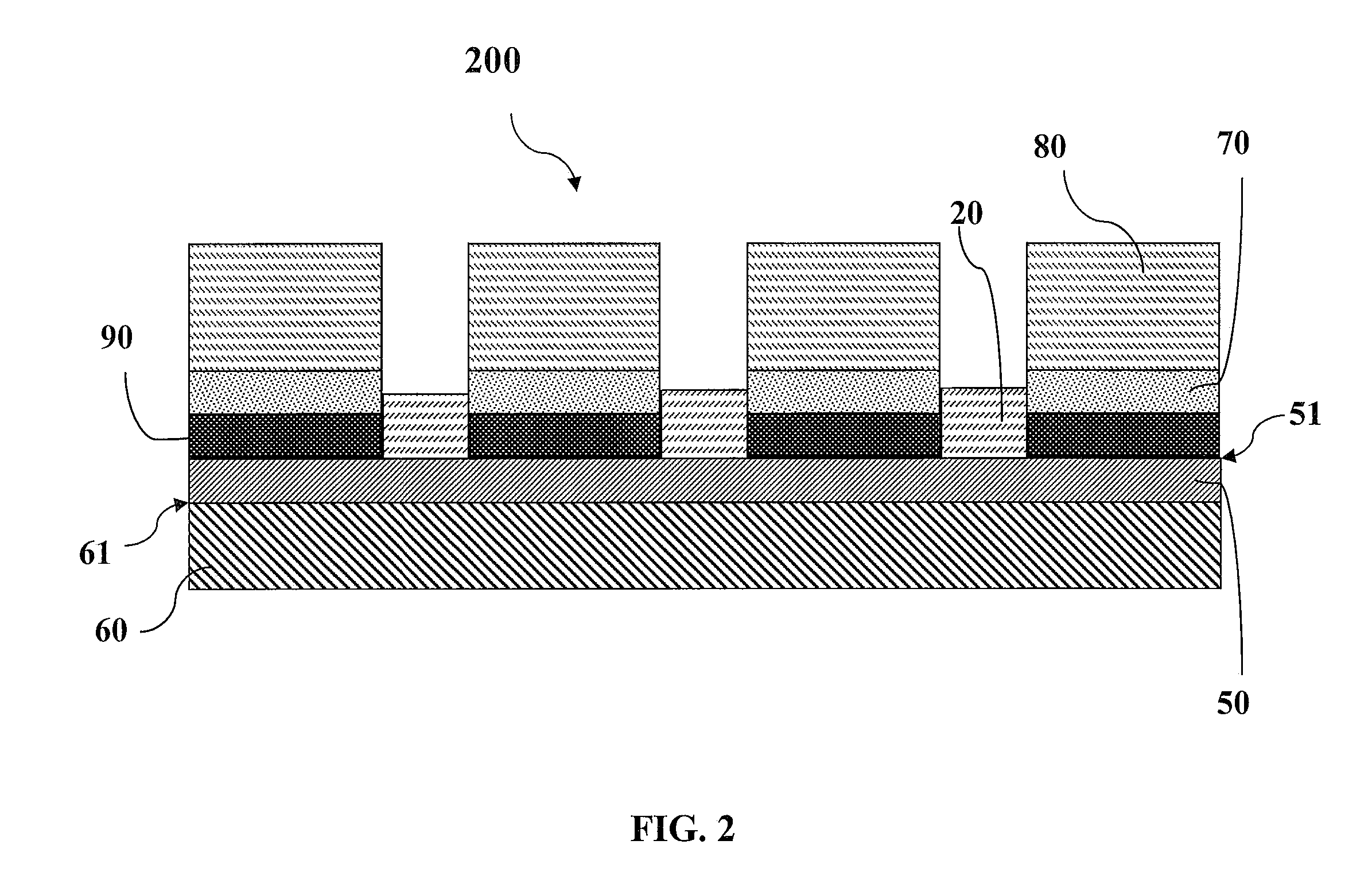
[0029]OVERVIEW: The present disclosure eliminates the filamentary etching process that has been ubiquitously used to fabricate multi-filamentary 2G HTS wire. More specifically, this disclosure is directed to multifilament HTS coated conductors and the etch-free method of fabricating the same. In accordance with one embodiment of the disclosure, the etch-free fabrication of a multifilament AC tolerant superconductor comprises the deposition of the at least one insulating filament prior to deposition of the superconducting material. In accordance with another embodiment of the disclosure, the etch-free fabrication of a multi-filament AC tolerant superconductor comprises the deposition of the superconducting material prior to the deposition of at least one insulating filament and subsequent heat treatment.

[0030]MULTIFILAMENT HTS: FIG. 1 shows a multifilament HTS structure that is in accordance with an exemplary embodiment of the present disclosure. The embodiment shown in FIG. 1 shows ...


PUM


Abstract

A high temperature superconductor structure including: a substrate on which at least one buffer layer is deposited, a superconductor layer on the buffer layer, the superconducting layer composed of superconductor material that forms at least two substantially parallel superconductor filaments that continuously extend along the length of the substrate wherein at least two superconductor filaments are separated from each other by at least one insulating strip wherein the insulating strip continuously extends along the length of the substrate and is composed of insulating material with a resistivity greater than about 1 mΩcm. Also disclosed are methods of producing high temperature superconductors.

Description

CROSS-REFERENCE TO RELATED APPLICATIONS[0001]This application claims the benefit under 35 U.S.C. §119(e) of U.S. Provisional Patent Application No. 61 / 358,369 filed Jun. 24, 2010, the disclosure of which is incorporated herein by reference.STATEMENT REGARDING FEDERALLY SPONSORED RESEARCH OR DEVELOPMENT[0002]Not applicable.BACKGROUND[0003]1. Field of the Disclosure[0004]The present disclosure relates generally to high temperature superconductors (HTS), and more specifically to a multi-filament, AC tolerant superconductor and method of forming the same.[0005]2. Background of the Disclosure[0006]The potential for high temperature superconductors (HTS) to efficiently transmit, generate, transform, use, and store electrical energy is recognized. In particular, more efficient electric power systems depend on more efficient wire technology. Past advancements permit brittle HTS materials to be formed into kilometer-length wires capable of transmitting about two hundred times the current tha...

Claims


Application Information

Patent Timeline
IPC IPC(8): H01B12/02H01B13/00
CPCH01L39/2461H01L39/143H10N60/203H10N60/0632H10N60/0801H10N60/80
Inventor SELVAMANICKAM, VENKATSAMBANDAM, SENTHIL
Owner SUPERPOWER INC
Learn More