
Interprocessor communication system and communication method, network switch, and parallel calculation system

Inactive Publication Date: 2011-12-29
NEC CORP
View PDF3 Cites 13 Cited by
  • Summary
  • Abstract
  • Description
  • Claims
  • Application Information

AI Technical Summary

Benefits of technology

[0021]According to the present invention, the data transferred between the nodes are allocated to the slots, which are created by dividing a unit of time into a plurality of sections; the data are transferred in a time-division multiplex manner. A process of transferring data to the input ports and output ports of the network switch is performed based on the information that is set in advance as the input slot correspondence management table and output slot correspondence management table. Therefore it is definitely possible to transfer data between the input ports and the output ports during a predetermined period of time. It is possible to guarantee communication bandwidths when communication takes place.
[0022]Moreover, each input port and output port of the network switch are able to set communication bandwidths separately using the input port management information and the output port management information, respectively. Since a minimum communication bandwidth is set for a requested communication bandwidth, low-power communication is possible.

Problems solved by technology

As the number of function nodes increases, the bus turns out to be a bottleneck in terms of performance when large amounts of data are simultaneously transferred.
Therefore, the transferring process may need to wait for an undetermined period of time depending on how crowded the to-be-transferred packets are.
Depending on a routing algorithm, a deadlock could occur.
However, even in this case, the transfer time is undetermined; it is difficult to guarantee a communication bandwidth in communication between function nodes when packets are transferred.

Method used


Image

  • Interprocessor communication system and communication method, network switch, and parallel calculation system
  • Interprocessor communication system and communication method, network switch, and parallel calculation system
  • Interprocessor communication system and communication method, network switch, and parallel calculation system

Examples


Embodiment Construction

[0037]The following describes in detail an exemplary embodiment of the present invention with reference to the accompanying drawings.

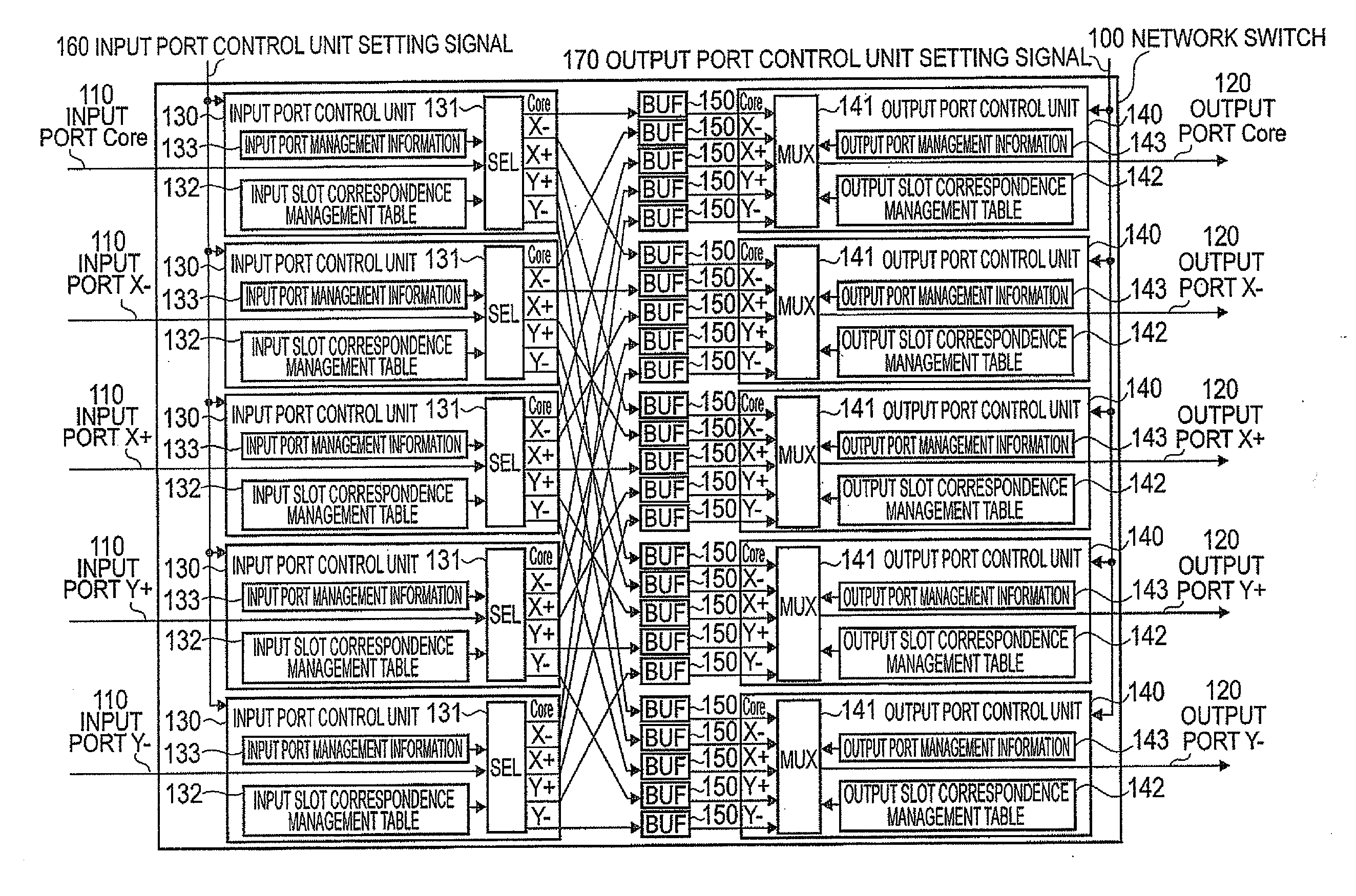
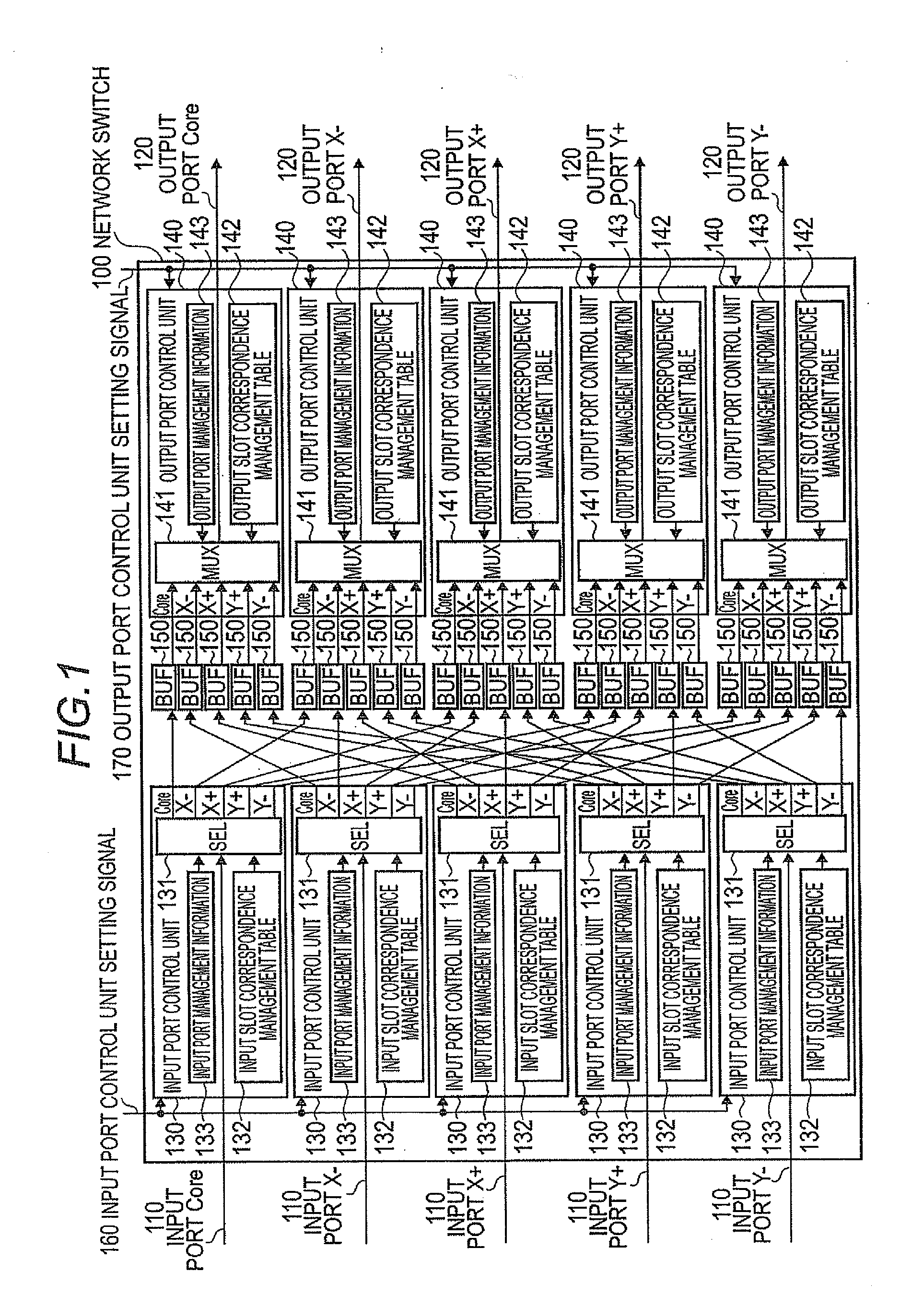
[0038]FIG. 1 is a block diagram showing the configuration of a network switch 100 using an interprocessor communication system according to an exemplary embodiment of the present invention. The network switch 100 shown in FIG. 1 includes a plurality of (five in FIG. 1) input ports 110; a plurality of (five in FIG. 1) output ports 120; input port control units 130, which correspond to each input port 110; output port control units 140, which correspond to each output port 120; and a plurality of buffers BUF150, which act as intermediaries in transferring data from each input port 110 to each output port 120. Among the above, a plurality of input ports 110 and input port control units 130 corresponds to a plurality of input units, a plurality of output ports 120 and output port control units 140 to a plurality of output units, and a plurality of buffers ...


PUM


Abstract

A network switch transfers data, which are to be transferred between nodes, in a time-division multiplex manner after allocating the data to slots, which are created by dividing a unit of time into a plurality of sections. An input unit includes a selection unit that selects a buffer unit according to an input slot in order to transfer the data input from the input port to the buffer unit, an input slot correspondence management table that stores a correspondence relationship between the input slots and the buffer units, and input port management information used to control a communication bandwidth of the input port. An output unit includes a multiplexing unit that selects the buffer unit according to an output slot in order for data, which is to be output to the output port, to be transferred from the selected buffer unit to the output port, an output slot correspondence management table that stores a correspondence relationship between the output slots and the buffer units, and output port manage information used to control a communication bandwidth of the output port.

Description

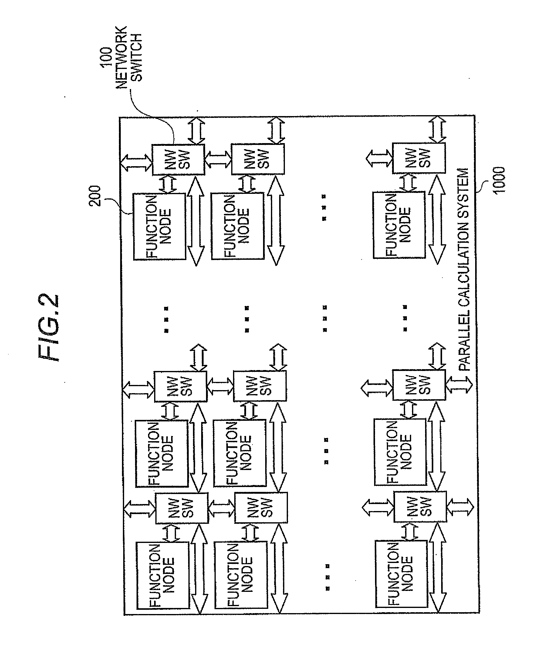
TECHNICAL FIELD[0001]The present invention relates to an interprocessor communication system and communication method of an inter-function-node communication type in a parallel processing (parallel calculation) system consisting of a plurality of processing (function) nodes, a network switch, and a parallel calculation system, and particularly to a communication system and communication method for guaranteeing a communication bandwidth between function nodes.BACKGROUND ART[0002]As a system LSI has become sophisticated and larger in size, many function nodes (processing constituents that require functions such as calculation, storage, or IO (Input / Output)) have been installed in the LSI. A plurality of function nodes described above can be regarded as a parallel calculation system in which the function nodes work together to perform one process. It is necessary to transfer data between a plurality of function nodes. When the number of function nodes is small, communication generally ...

Claims


Application Information

Patent Timeline
IPC IPC(8): H04L12/50
CPCH04L49/109H04L49/101
Inventor KAJIHARA, NOBUKI
Owner NEC CORP
Learn More