
Cutting tool

a cutting tool and cutting technology, applied in the field of cutting tools, can solve the problems of reducing the effective application bias potential, growing exclusively or primarily amorphous structures,

Active Publication Date: 2011-12-22
WALTER AG
View PDF7 Cites 14 Cited by
  • Summary
  • Abstract
  • Description
  • Claims
  • Application Information

AI Technical Summary

Benefits of technology

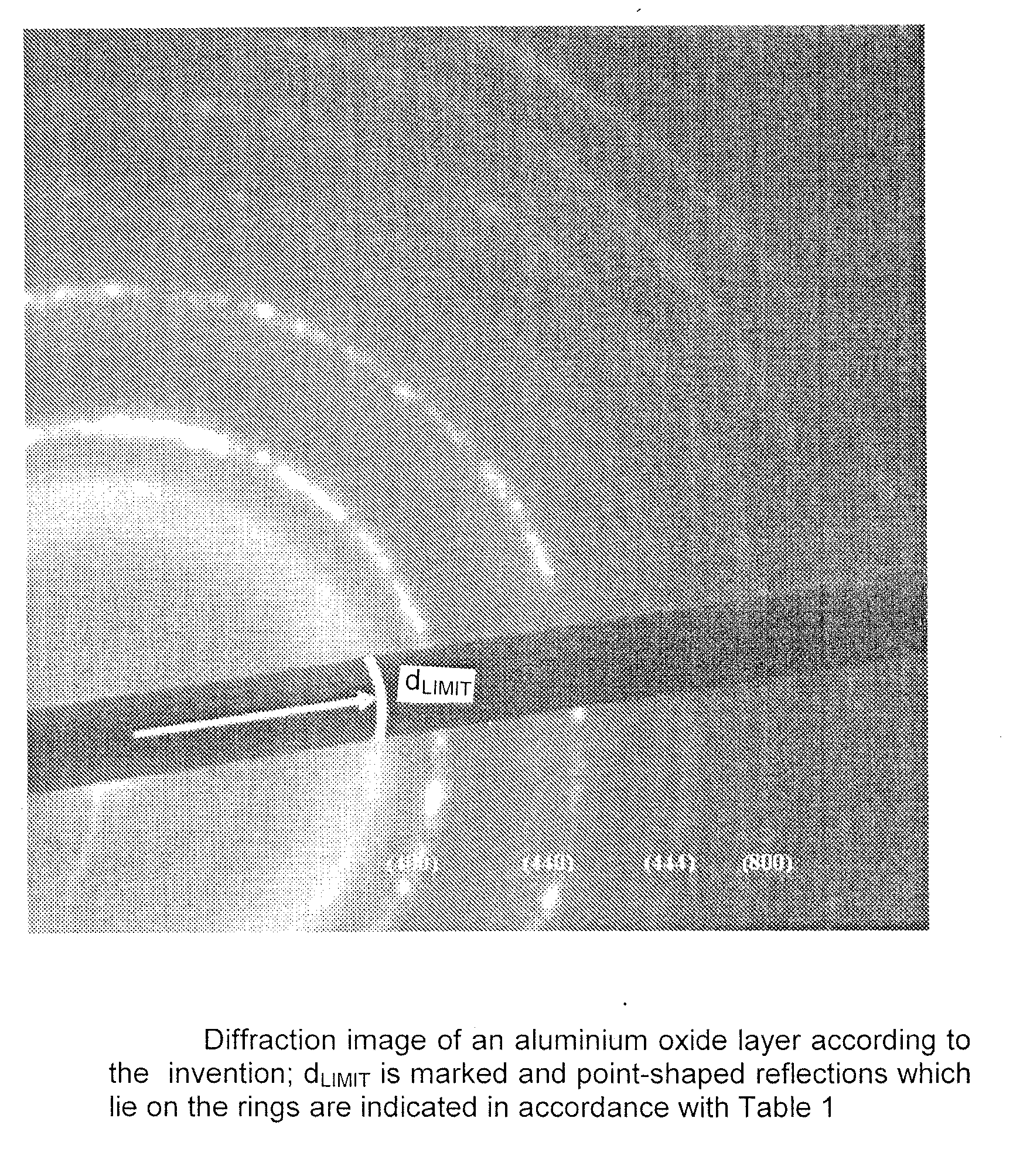
The invention is a cutting tool with a single-layer or multi-layer coating applied to a substrate. The coating includes a metal oxide layer with a unique structure that can be detected by electron diffraction. The metal oxide layer has a grain structure with structural disorder within the grains, which is characterized by point-shaped reflections in the electron diffraction images. The intensity distribution of the reflections is similar to that of amorphous structures, but there are no point-shaped reflections up to a certain grain size. The new structure is defined by the electron diffraction data and is distinct from pure crystalline or polycrystalline structures, amorphous structures, or structures with polycrystalline components in an amorphous matrix. The invention provides a tool with improved performance and durability.

Problems solved by technology

When applying insulating layers using the PVD process, which applies for example to a large number of metal oxide compounds, the effectively applied bias potential is reduced during the growth process with increasing layer thickness, because of the insulating properties of the layer material, and that worsens the growth conditions at the layer surface and in addition can ultimately lead to exclusively or primarily amorphous structures being grown.

Method used


Image

  • Cutting tool
  • Cutting tool

Examples


example 1

[0077]

Metal oxide: Al2O3PVD process:dual magnetrontarget:Al rectangular target (81 cm × 16 cm)deposition:substrate temperature: 550° C.substrate bias voltage:−150 volts (DC pulsed  100 kHz, 2 μs off-time)power:   20 kWoxygen flow:  150 sccm with 0.6 PaAr gaslayer thickness:  2.1 μm

example 2

[0079]

Metal oxide: (Al,Cr)2O3PVD process:dual magnetrontarget:Al / Cr— (70 / 30 atomic %) rectangular target (81 cm ×16 cm)deposition:substrate temperature: 550° C.substrate bias voltage:−100 volts (DC pulsed   70 kHz, 4 μs off-time)power:   20 kWoxygen flow:  150 sccm with 0.2 PaAr gaslayer thickness:  3.3 μm


PUM

PropertyMeasurementUnit
lattice plane spacingaaaaaaaaaa
grain sizesaaaaaaaaaa
thicknessaaaaaaaaaa

Abstract

The invention relates to a cutting tool having a substrate base body and a single or multi-layered coating attached thereupon, wherein at least one layer of the coating is a metal oxide layer produced in the PVD process or in the CVD process and the metal oxide layer has a grain structure wherein there is structural disorder within a plurality of the existing grains that are characterized in that in electron diffraction images of the grains, point-shaped reflections occur up to a maximum lattice spacing dGRENZ and for lattice spacing greater than dGRENZ no point-shaped reflections occur, but rather a diffuse intensity distribution typical for amorphous structures.

Description

SUBJECT OF THE INVENTION [0001]The invention concerns a cutting tool having a substrate main body and a single-layer or multi-layer coating applied thereto, wherein at least one layer of the coating is a metal oxide layer produced in the PVD process or in the CVD process.BACKGROUND OF THE INVENTION[0002]Cutting tools comprise a main body made for example from carbide metal, cermet, steel or high-speed steel. Frequently a single-layer or multi-layer coating is applied to the main body to increase the service lives or also to improve the cutting properties. That coating includes for example metallic hard material layers, oxide layers or the like. CVD processes (chemical vapour deposition) and / or PVD processes (physical vapour deposition) are employed to apply the coating. A plurality of layers within a coating can be applied exclusively by means of CVD processes, exclusively by means of PVD processes or by a combination of those processes.[0003]In regard to the PVD processes a distinc...

Claims


Application Information

Patent Timeline
Patent Type & Authority Applications(United States)
IPC IPC(8): B32B15/04B32B33/00C23C14/34C23C14/24C23C14/35C23C14/46C09D1/00B32B5/16C01B13/00C01F7/02C01G37/02C01B33/113C01F17/00C01G53/04C01G35/00C01G25/02C01G41/02C01G39/02C01G27/02C01G31/02B32B9/00B82Y30/00
CPCC23C14/081C23C14/083C23C30/005B23B27/14Y10T428/257B23B2228/105C23C14/08C23C16/40Y10T428/265B23B2228/08B23B27/02C23C14/06C23C16/30
Inventor SCHIER, VEITEIBL, OLIVERENGELHART, WOLFGANG
Owner WALTER AG
Learn More