Thermal solar energy collector

a solar energy collector and solar energy technology, applied in the safety of solar heat collectors, solar heat collector details, light and heating apparatus, etc., can solve the problems of air quickly oxidizing the external surface of air, reducing the effective collection of heat, and transferring heat to the heat-conducting fluid,

Inactive Publication Date: 2011-12-22
UNIV MADRID POLITECNICA
View PDF9 Cites 10 Cited by
  • Summary
  • Abstract
  • Description
  • Claims
  • Application Information

AI Technical Summary

Problems solved by technology

In these two patents, two especially serious problems of this panel or collector arrangement or configuration are evident: as these tubes are bare, the natural convection of the circulating air extracts a lot of heat from the irradiated surface, thus decreasing the effectively collected heat, that is, transferred to the heat-conducting fluid, with which the performance of the collector is low or very low; and besides, the oxygen of the air may quickly oxidize the external surface of the hot tube, which will have to be painted with a substance having a high solar absorptivity and a low emissivity, properties which are degraded when the oxygen chemically reacts with said especial paint layer.
This solution, however, has a problem, namely, that the glass of the transparent cover has to work with pressure differences between its walls of approximately one atmosphere, that is, about 100,000 pascals.
This pressure difference is very high for a material having a very low elastic limit, such as glass (and it would be even worse for some transparent plastics, because they would also have to withstand temperatures much higher than room temperature, though not as high as the ones of the radiation absorbent surface).
This means that the dimensions of the glass cover (or the cover in general), will be very limited by the internal mechanical stresses induced by the aforementioned pressure difference.
The glass cover could be very thick, to increase the transverse moment of inertia, thus decreasing the internal stress needed for balancing the induced bending moment, but this possibility presents, in turn, another inconvenience, since there is not any absolutely transparent glass, and the thicker the glass is, the greater the amount of absorbed radiation within itself there would be, which generates higher internal temperatures, and a greater gradient for it, because it is only refrigerated through the external wall, which generates the appearance of mechanical stress induced by thermal differences, that may also be larger than the ones produced by the external and internal pressure difference.
Along with the problems highlighted, another equally important problem should be noted, namely, that the expansions produced when the collector elements go from room temperature to the operation one, which may imply an increase of 500° C. or equal Kelvin in the SI system.

Method used


Image

  • Thermal solar energy collector
  • Thermal solar energy collector
  • Thermal solar energy collector

Examples


Embodiment Construction

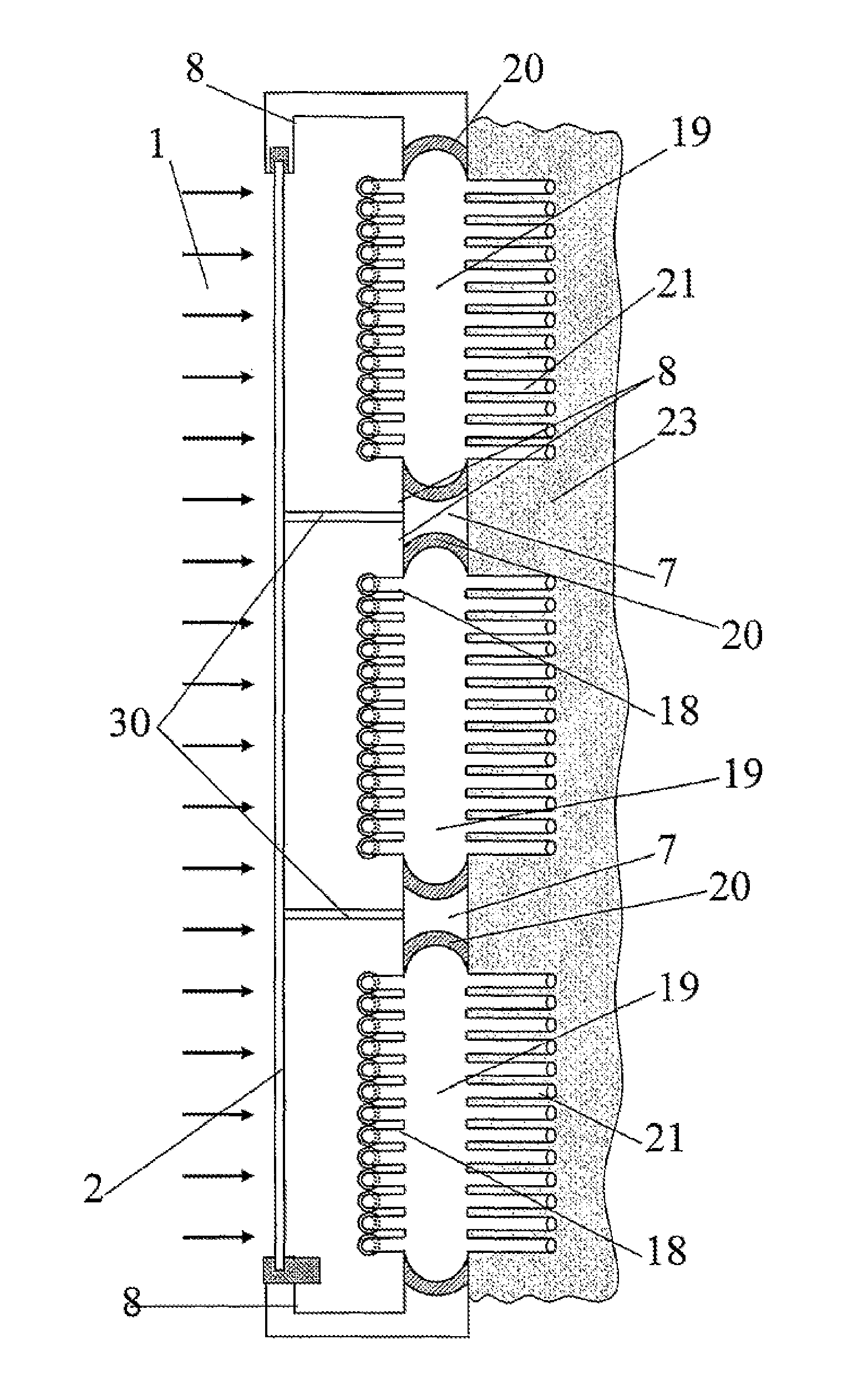
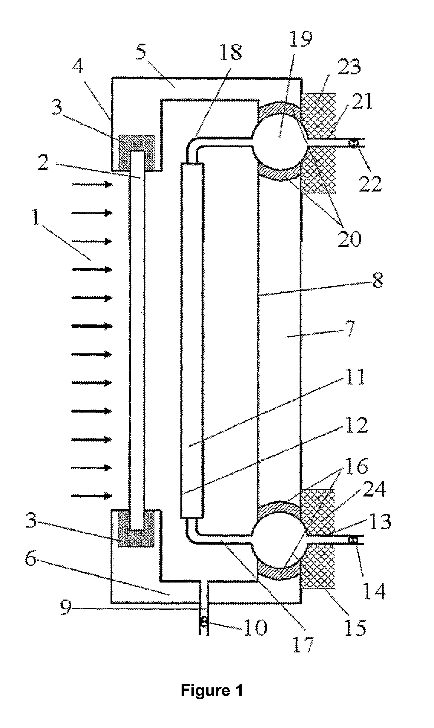
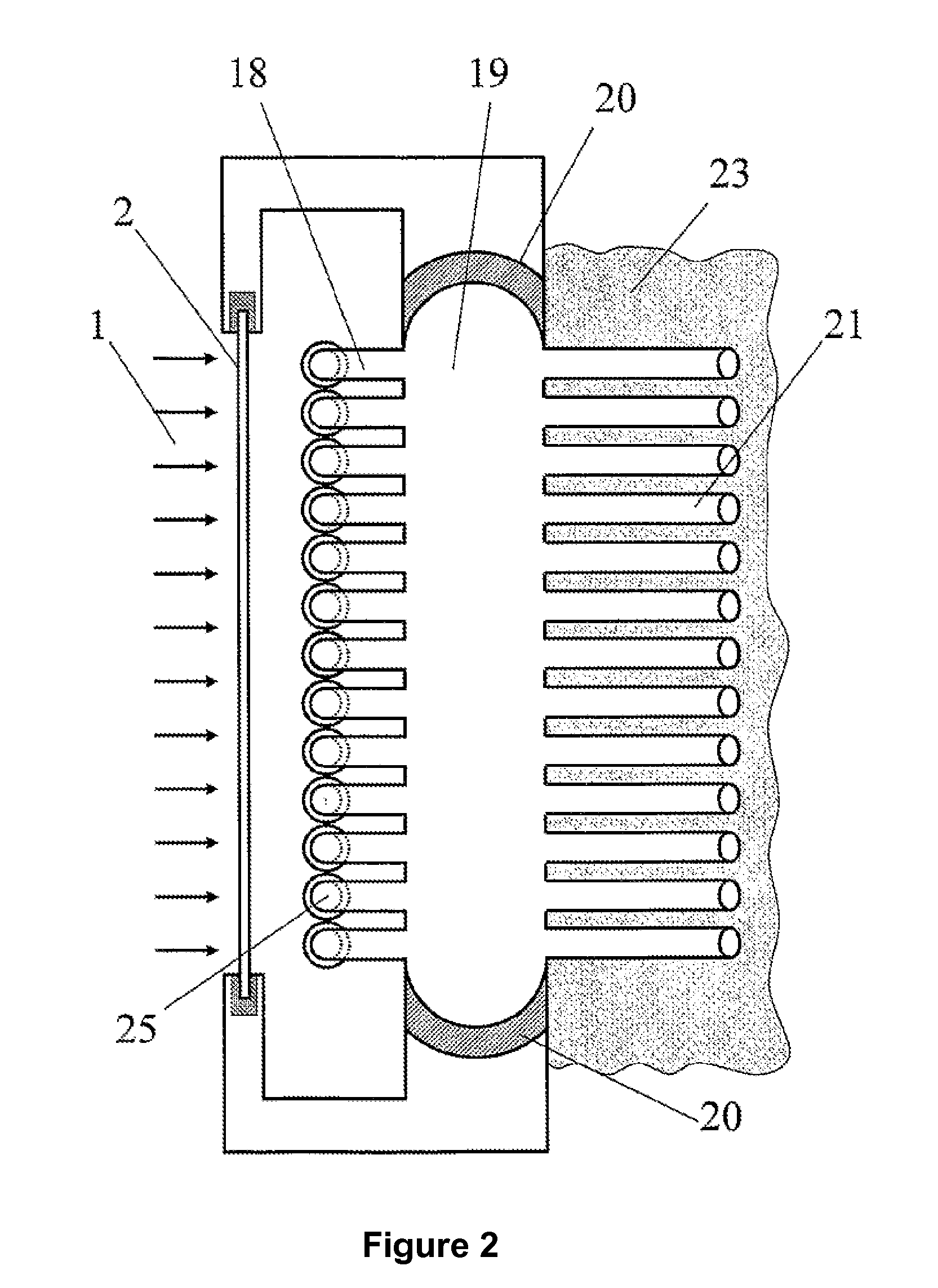
[0009]The invention consists in placing the radiation absorbent surface, and its matrix or supporting body, inside of which the heat-conducting fluid flows, in the interior of a big airtight box or receptacle that has a wall constituted by a transparent cover which is penetrated by the radiation to be absorbed; and the rest of the walls will be made of materials which will include mechanically strong structures, as well as thermal insulation; proposing an arrangement of the essential thermal component in such a way that it easily allows the assimilation of its expansions without altering the airtightness of the receptacle or box, which will be, in a first option of the invention, in vacuum conditions.

[0010]The component arrangement helps to minimize heat losses by conduction and convection towards the exterior; and the chemical aggression to the external layer of the radiation absorbent surface is minimized as well, thanks to the internal vacuum and the absence of oxygen. As an alte...


PUM


Abstract

Thermal solar energy collector, in which a solar radiation absorption panel, inside which the heat-conducting fluid flows, is situated inside a parallelepipedal box, with an opening having a transparent cover at the front, which may be doubled so as to leave an atmospheric space in the middle. The rear wall of the box has a system of seals and reservoirs which are inset in the wall so that they accommodate the expansion and contraction of vertical tubes of the panel and horizontal connections by means of gentle changes in curvature of the tube bends and slight rotations of the reservoirs, with the addition of a system for filling the box with an inert gas, the pressure of which may be chosen from a range of between a thousandth of an atmosphere and one atmosphere, there being provided for this purpose an external gas circuit, with low- and high-pressure tanks, an intermediate compressor.

Description

TECHNICAL FIELD OF THE INVENTION[0001]The invention refers to the field of thermal solar energy, particularly to the one that uses the concentration of source radiation, reflected by some steerable mirrors, and striking on some collectors that absorb part of said radiation to reach high temperature in the beneficial good, which generally materializes in a heat-conducting fluid that carries the solar heat absorbed to a thermodynamic cycle. Within this field the invention refers to collectors themselves, where there is a flat or curve surface which absorbs radiation, and which constitutes the external surface of a body inside which the aforementioned heat-conducting fluid flows. The invention refers to the configuration and constitution of these collectors, to maximize the solar energy collection performance, while they are provided with an intrinsic robustness, which allows them to withstand the thermomechanical effects produced by great variations in temperature and other thermodyna...

Claims


Application Information

Patent Timeline
Patent Type & Authority Applications(United States)
IPC IPC(8): F24J2/24F24J2/48F24J2/05F24S10/40F24S10/70F24S10/75F24S20/20
CPCF24J2/265F24J2/4636F24J2/465F24J2002/502Y02E10/44F24J2/07F24J2/51F24J2/4616F24J2/463F24J2/4645F24J2/4647F24J2/507F24J2/345F24S10/753F24S20/20F24S40/46F24S40/58F24S40/80F24S60/30F24S80/30F24S80/453F24S80/54F24S80/60F24S80/70F24S2080/502Y02E10/40
Inventor MARTINEZ-VAL PENALOSA, JOSE MARIA
Owner UNIV MADRID POLITECNICA
Why Eureka
Try Eureka