Speed or torque probe for gas turbine engines

a technology of speed or torque and gas turbine engine, which is applied in the direction of work measurement, measurement devices, instruments, etc., can solve the problems of additional modulations or microphonies, the output of variable reluctance sensors is not working properly, and the pole piece is significantly damaged by external vibration, so as to minimise the transfer of strain and reduce the effect of strain transfer

Active Publication Date: 2011-12-22
WESTON AEROSPACE
View PDF4 Cites 15 Cited by
  • Summary
  • Abstract
  • Description
  • Claims
  • Application Information

AI Technical Summary

Benefits of technology

[0024]By fixing the pole piece to the side wall of the sensor housing, strain in the pole piece as a result of external vibration is significantly reduced. The strain is effectively transferred to the side wall of the housing rather than along the length of the pole piece. Preferably, the pole piece comprises a longitudinal shaft proximate to the front face of the housing, wherein the conductive wire is wrapped around the longitudinal shaft, and a head end remote from the front face of the housing, wherein the head end is fixed to the side wall of the housing.
[0025]Preferably, the pole piece is rigidly fixed to a plurality of points on the housing. By connecting the pole piece to the housing at a plurality of points or over an extended area, the transfer of strain can be increased. “Rigidly fixed” in this context means more than simply held in place through an interference fit with other components of the sensor or with an encapsulation material. It requires a positive fixing means. The pole piece may be fixed to the side wall or side walls of the housing by any suitable means, such as welding, brazing or by using some mechanical fixing, such as a screw fitting. It is also possible to include a rigid intermediate structure between the pole piece and the housing to provide the rigid fixing. The pole piece is then directly fixed to the intermediate structure and the intermediate structure directly fixed to the housing. This may have advantages in the assembly of the sensor.
[00...

Problems solved by technology

If the noise amplitude exceeds the trigger threshold of the engine controls, the torque or speed measuring system will not function properly as the noise will be interpreted as an additional zero crossing, and in extreme circumstances the controls may shut the engine down if the torque or speed measurement is a primary engine function.
One major cause of noise in the output from variable reluctance sensors, producing the additional modulations or microphony, is vibration from the surrounding environment.
The reason that vibrations cause noise in the output signal is the affect that they have on the pole piece.
Vibration in the sensor environment can cause stress in the pole piece that alters its magnetic permeability.
The stress energy created in the pole piece causes strain, which affects the permeability and so alters the reluctance of the device.
This additional induced ...

Method used


Image

  • Speed or torque probe for gas turbine engines
  • Speed or torque probe for gas turbine engines
  • Speed or torque probe for gas turbine engines

Examples


Embodiment Construction

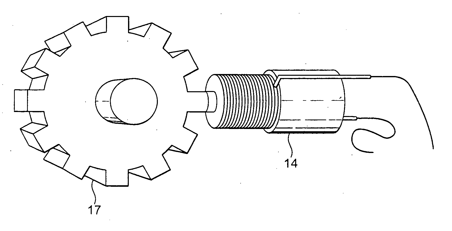
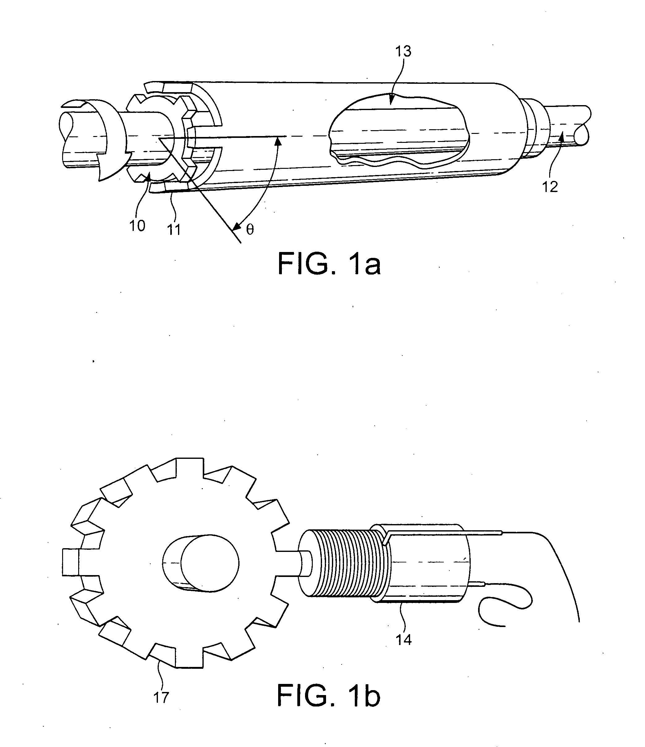
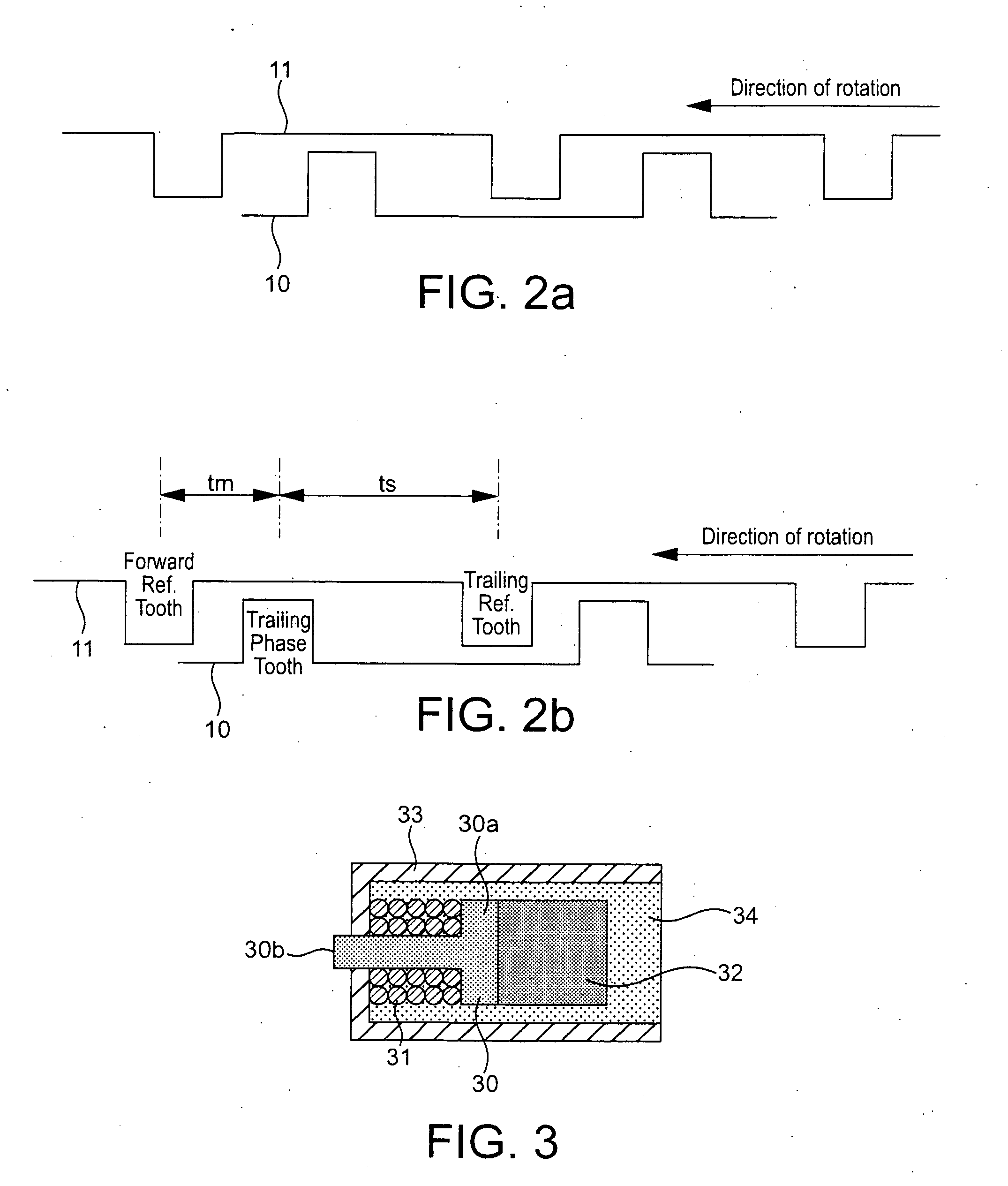
[0053]The basic arrangement for a variable reluctance sensor for detecting speed or torque in a gas turbine engine or gear box connected to a gas turbine engine has been described previously with reference to FIGS. 1 to 3. The problem of unwanted microphony in the output signal from such variable reluctance sensors, resulting from strain in the magnetic pole piece 30, has also been described.

[0054]FIG. 6 illustrates a variable reluctance sensor as shown in FIG. 3, but illustrating the direction of the strain in the pole piece 30, which affects the nature of the output signal from conductive wire 31. The pole piece is formed from a soft magnetic material, is roughly T-shaped in cross-section and has a longitudinally extending shaft around which the conductive wire is wound and a rear head, against which the permanent magnet 32 is positioned. Current induced in the wire 31 as result of changes in the reluctance of the circuit formed by the magnetic pole piece, the phonic wheel, and ai...


PUM


Abstract

There is provided a variable reluctance sensor for sensing the speed or torque of a shaft in a gear box or gas turbine engine, comprising a magnetic pole piece a conductive wire wrapped around the pole piece a housing surrounding the pole piece, the housing having a front face and at least one side wall, wherein, in use, the front face is positioned proximate to an object to be sensed wherein the pole piece is rigidly fixed to the side wall of the housing. This arrangement reduces microphony in the sensor.

Description

FIELD OF THE INVENTION[0001]The present invention relates to variable reluctance probes used for measuring the speed and torque applied to rotating shafts. Probes of this type are typically found in gas turbine engines or in gear boxes used in aircraft.BACKGROUND TO THE INVENTION[0002]Variable reluctance sensors are used to monitor both the speed of rotating shafts and the torque loading on shafts in gas turbine engines and gear boxes connected to gas turbine engines. For example, FIG. 1 illustrates an assembly for monitoring the torque loading on a power transmission shaft between a gas turbine and the power gearbox that drives the propeller.[0003]When a load is applied to a power transmission shaft it will twist. For a known modulus of elasticity and at a constant temperature, the amount of twist (A) is proportional to the torque transmitted. This basic principle is used to measure torque.[0004]The assembly shown in FIG. 1a comprises two intermeshed phonic wheels 10, 11, attached ...

Claims


Application Information

Patent Timeline
IPC IPC(8): G01L3/02
CPCG01L3/109G01P3/488G01P1/026G01D3/036G01D5/2006
Inventor BODIN, ROBERT MICHAEL GEORGE
Owner WESTON AEROSPACE
Why Eureka
Try Eureka