
Distortion sensor and deformed shape measuring method

Active Publication Date: 2011-12-15
TOKAI RUBBER IND LTD
View PDF8 Cites 25 Cited by
  • Summary
  • Abstract
  • Description
  • Claims
  • Application Information

AI Technical Summary

Benefits of technology

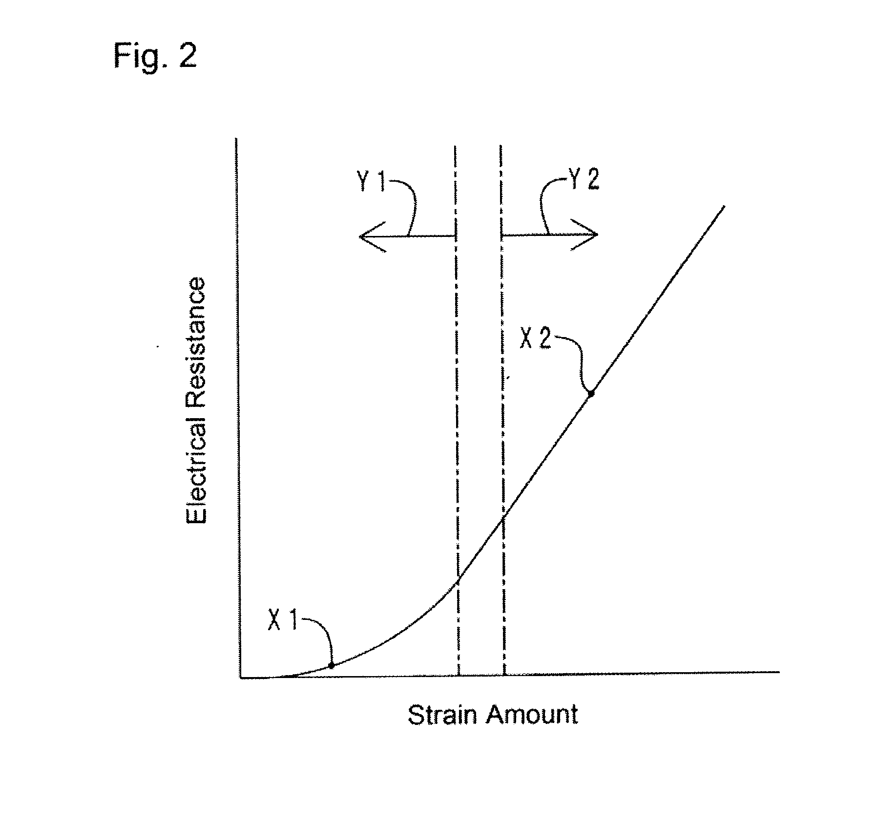
[0012]In the sensor body, which constitutes the bending sensor according to the present invention, the conductive filler particles are filled in the matrix resin at a filling rate of 30% by volume or more. Here, the filling rate of the conductive filler particles is a value when a volume of the sensor body is 100% by volume. Due to the high filling rate of the conductive filler particles, three-dimensional conductive paths are formed in the sensor body by contact among the conductive filler particles. That is, the sensor body has a high conductivity in a no-load state, and the electrical resistance increases as a magnitude of a deformation increases.
[0074]In the deformed shape measurement method of the present invention, the bending sensor is partitioned into a plurality of measurement sections. The deformed shape of the entire bending sensor, that is, the deformed shape of the measured object, is measured by joining together the deformed shapes of the measurement sections. According to the deformed shape measurement method of the present invention, by using the bending sensor of the present invention, a deformed shape of a measured object can be easily and dynamically measured. Further, when the number of arranged electrodes is increased, the measurement sections can be more finely partitioned. This allows the bending sensor, that is, the measured object to be more finely partitioned and the shapes of the sections be respectively measured. As a result, the deformed shape of the bending sensor, that is, the measured object, can be accurately calculated.

Problems solved by technology

However, it takes time from an input of a strain until the parent material elastically deforms.
Therefore, in detection of a bending deformation in the elastic region of the parent material, a response is delayed by the time required for the elastic deformation of the parent material.
In particular, for a fast bending deformation, the response delay further increases and thus the detection accuracy is likely to further decrease.
Therefore, the input speed of the strain and the temperature of the atmosphere also contribute to the decrease in the detection accuracy.

Method used


Image

  • Distortion sensor and deformed shape measuring method
  • Distortion sensor and deformed shape measuring method
  • Distortion sensor and deformed shape measuring method

Examples


first embodiment

Configuration of Bending Sensor

[0128]First, a configuration of a bending sensor according to the present embodiment is explained. FIG. 3 illustrates a front view of the bending sensor. FIG. 4 illustrates a cross sectional view taken along a line IV-IV shown in FIG. 3. FIG. 5 illustrates an enlarged view of an area within a circle V shown in FIG. 4. For convenience of explanation, a right half of a cover film is removed from the illustration shown in FIG. 3. As FIGS. 3 and 4 illustrate, a bending sensor 1 has a base material 10, a sensor body 11, electrodes 12a-12i, wirings 13a-13i, and a cover film 14.

[0129]The base material 10 is made of a polyimide, and has a belt-like shape extending in a left-right direction. The base material 10 has a thickness of about 300 μm. At a right end of the base material 10, a connector 15 is arranged.

[0130]The sensor body 11 has a belt-like shape extending in the left-right direction. The sensor body 11 has a thickness of about 100 The sensor body 11...

embodiment 1

(1) Embodiment 1

[0230]The sample of the embodiment 1 had the same configuration as that of the bending sensor according to the fifth embodiment. Further, the detection sections 710-714 each had a width of 1 mm in a transverse0 direction and a total length of 50 mm in a longitudinal direction.

embodiment 2

(2) Embodiment 2

[0231]The embodiment 2 was different from the embodiment 1 in that the number of arranged detection sections 710-714 was not 5, but 10, and in that the width in the transverse direction of each of the detection sections 710-714 was not 1 mm, but 0.5 mm. Other aspects were the same.


PUM


Abstract

Provided are a bending sensor that is less dependent on an input speed of a strain and in which a response delay is unlikely to occur, and a deformed shape measurement method using the bending sensor. The bending sensor is configured to include a base material; a sensor body arranged on a surface of the base material and containing a matrix resin and conductive filler particles filled in the matrix resin at a filling rate of 30% by volume or more, and in which three-dimensional conductive paths are formed by contact among the conductive filler particles, and electrical resistance increases as an deformation amount increases; an elastically deformable cover film arranged so as to cover the sensor body; and a plurality of electrodes connected to the sensor body and capable of outputting electrical resistances. In the sensor body, cracks are formed in advance in such a direction that the conductive paths are cut off during a bending deformation.

Description

TECHNICAL FIELD[0001]The present invention relates to a bending sensor capable of detecting bending deformation of a measured object and a deformed shape measurement method using the bending sensor.BACKGROUND ART[0002]For example, as a means for detecting deformation of a member and a magnitude of a load acting on the member, a flexible sensor using an elastomer or a resin has been proposed. The sensor has a sensor body in which conductive filler particles are mixed in the elastomer or the resin. For example, in a sensor body disclosed in Patent Documents 1 and 2, spherical conductive filler particles are mixed at a high filling rate in an elastomer or a resin. Therefore, in the sensor body in a state in which a load is not applied (which may be referred to as a “no-load state” as appropriate in the following), 3-dimentional conductive paths are formed by contact among conductive filler particles. Therefore, the sensor body has a high electrical conductivity in the no-load state.[00...

Claims


Application Information

Patent Timeline
IPC IPC(8): G06F15/00G01B7/16
CPCG01B7/18G01L1/205G01M5/0041H01C17/06586H01C10/106H01C17/0652G01M5/0083G01B1/00G01B7/16
Inventor SAITOU, YUUKIMURAYAMA, MASARUHAYAKAWA, TOMONORIHASEGAWA, KOICHISHIBATA, TETSUYOSHI
Owner TOKAI RUBBER IND LTD
Learn More