Dye application for confocal imaging of cellular microstructure

a cellular microstructure and confocal imaging technology, applied in the field of diagnosis, can solve the problems of limited ability to obtain confocal images of normal and diseased tissue in vivo, application of confocal microscopic imaging techniques, and inability to examine living tissue with confocal microscopy

Active Publication Date: 2011-12-08
UNIV OF UTAH RES FOUND
View PDF11 Cites 30 Cited by
  • Summary
  • Abstract
  • Description
  • Claims
  • Application Information

AI Technical Summary

Benefits of technology

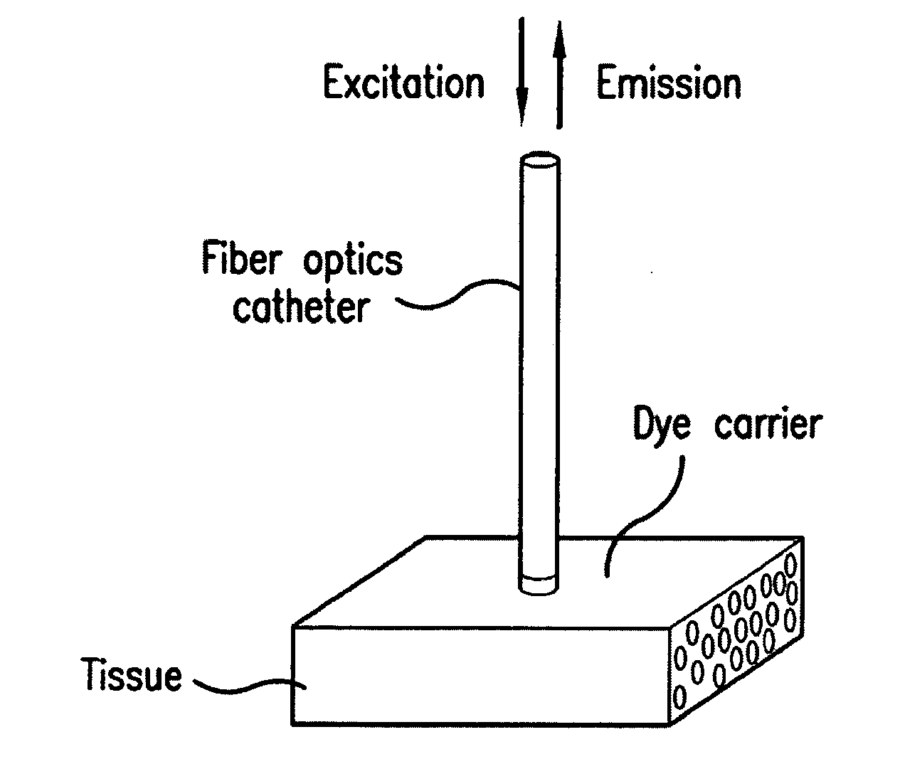
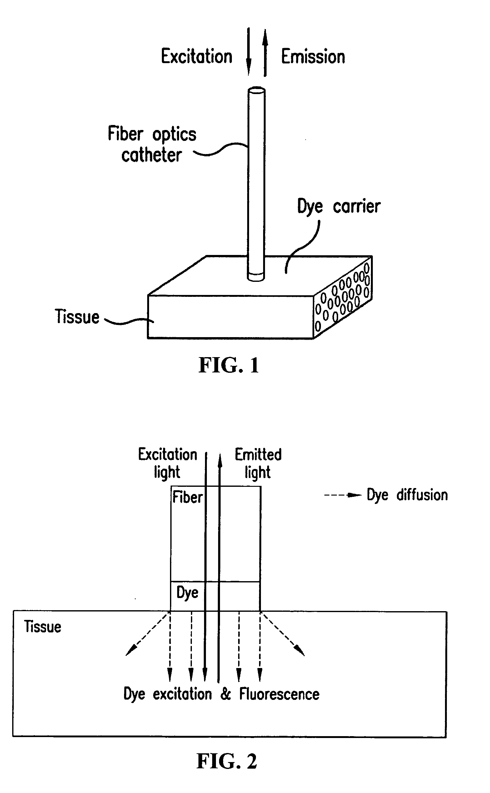
[0010]In operation, the distal end portion of the catheter is steered through blood vessels or body cavities to a location adjacent to a tissue of interest. Subsequently, the dye carrier is brought in contact with the desired vessel or cavity surfaces, respectively. After contact of the dye carrier with the surfaces, the fluorescent dye(s) are allowed to diffuse from the dye carrier...

Problems solved by technology

Typically, confocal microscopy has not been used to examine living tissue because of the need for close association between microscope instrumentation and the imaged tissue, toxic or expensive fluorescent dyes for image contrast, and relatively long image acquisition times. Despite these challenges, confocal microscopy techniques have been shown to provide valuable diagnostic information for various disease states.
The ability to obtain confocal...

Method used


Image

  • Dye application for confocal imaging of cellular microstructure
  • Dye application for confocal imaging of cellular microstructure
  • Dye application for confocal imaging of cellular microstructure

Examples


Embodiment Construction

[0031]The present invention can be understood more readily by reference to the following detailed description, examples, drawing, and claims, and their previous and following description. However, before the present devices, systems, and / or methods are disclosed and described, it is to be understood that this invention is not limited to the specific devices, systems, and / or methods disclosed unless otherwise specified, as such can, of course, vary. It is also to be understood that the terminology used herein is for the purpose of describing particular aspects only and is not intended to be limiting.

[0032]The following description of the invention is provided as an enabling teaching of the invention in its best, currently known embodiment. To this end, those skilled in the relevant art will recognize and appreciate that many changes can be made to the various aspects of the invention described herein, while still obtaining the beneficial results of the present invention. It will also...


PUM


Abstract

A system and method for confocal imaging of tissue in vivo and in situ, e.g., for minimally invasive diagnosis of patients. A catheter is provided that has a dye carrier coupled to the distal end of a fiber optics bundle, which allows for the introduction of at least one fluorescent dye therein the dye carrier into a portion of the tissue of interest of a subject or patient when the dye carrier is selectively brought into contact with the portion of the tissue of interest. The resulting confocal images permit the acquisition of diagnostic information on the progression of diseases at cellular/tissue level in patients. Furthermore, a system for ECG-triggered image acquisition is provided.

Description

CONTINUITY[0001]This application claims priority to and the benefit of U.S. Provisional Patent Application No. 61 / 137,876, which was filed on Aug. 4, 2008, the entirety of which is incorporated herein by reference.FIELD OF THE INVENTION[0002]This invention generally relates to diagnosis of a large class of diseases, which affect the microstructure of tissues, the size and shape of cells, and the arrangement of cells. Alterations of tissues and cells have been reported for cardiac diseases, e.g., hypertrophy, infarction and ischemia, which are the leading cause of death in most developed countries.BACKGROUND[0003]Currently, magnetic resonance (MR), ultrasonic (US) and computer tomographic (CT) imaging techniques are major tools for clinical diagnosis of diseases and evaluation of therapeutic interventions. Confocal microscopic imaging techniques constitute a state-of-the-art approach to study progression of diseases in ex vivo preparations of tissue and cells of animal models and to ...

Claims


Application Information

Patent Timeline
IPC IPC(8): A61B6/00A61B5/00
CPCA61B5/0068A61B5/0071A61B5/0084A61B5/6852A61B5/7285G02B21/0076A61B1/0008A61B1/043G02B21/0028G02B21/0032A61K49/0021
Inventor SACHSE, FRANK B.BRIDGE, JOHN H.HITCHCOCK, ROBERT
Owner UNIV OF UTAH RES FOUND
Why Eureka
Try Eureka