Solar battery module
a solar battery and module technology, applied in the field of solar battery modules, can solve the problems of unnecessary light pollution, small light that is reflected from the low-reflectance back sheet and the module glass and is inputted again into the cells, etc., and achieve the effect of suppressing light pollution and high outpu
- Summary
- Abstract
- Description
- Claims
- Application Information
AI Technical Summary
Benefits of technology
Problems solved by technology
Method used
Image
Examples
first embodiment
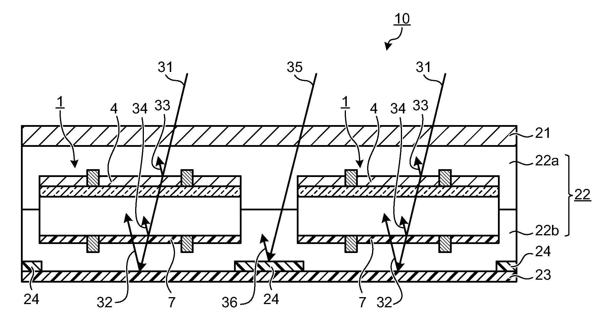
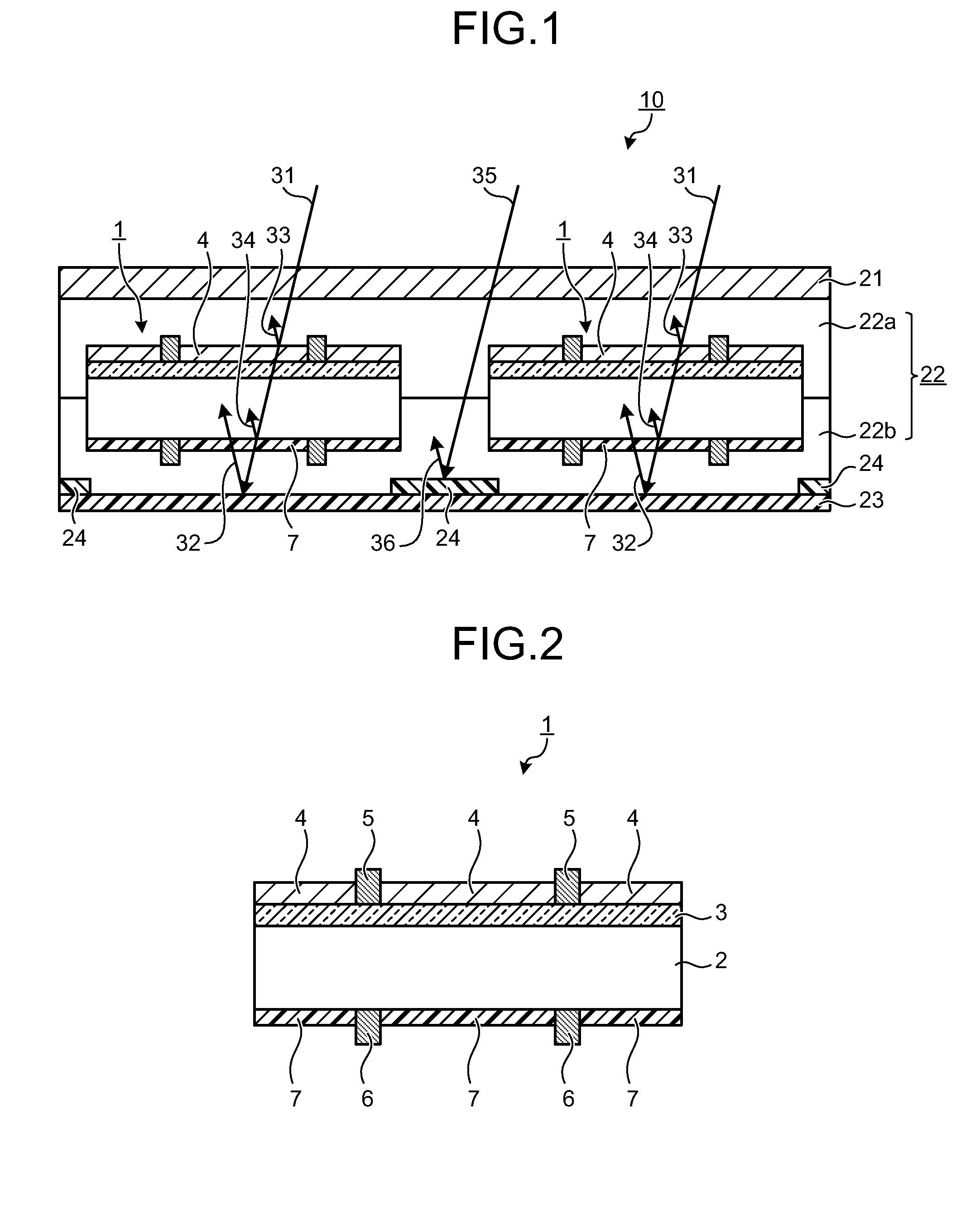
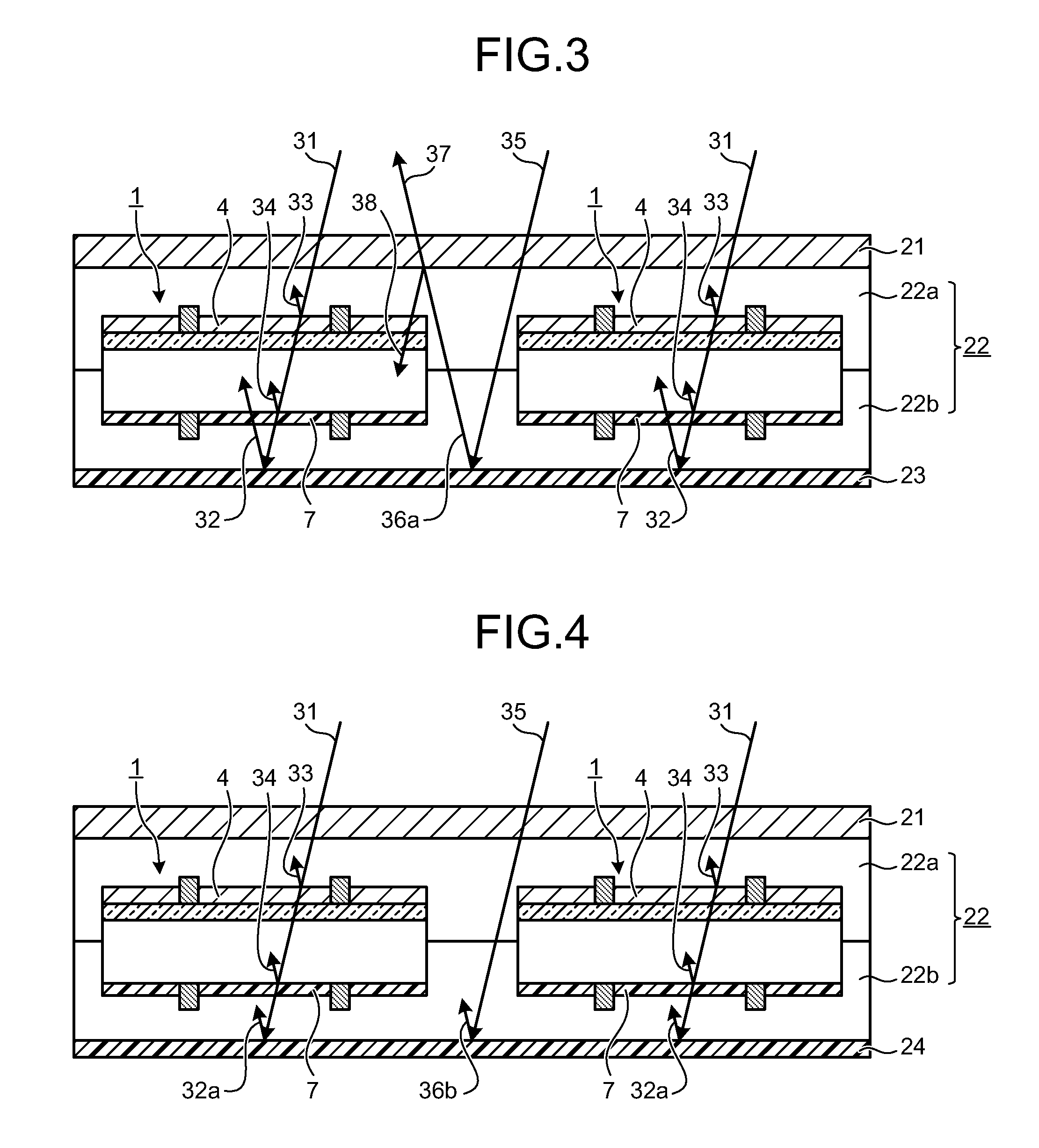
[0054]FIG. 1 is a cross-sectional view of a configuration of a solar battery module according to a first embodiment of the present invention. A solar battery module 10 (hereinafter, “module 10”) according to the present embodiment has a configuration (not shown) such that a plurality of back-surface passivation solar battery cells 1 (hereinafter, “cells 1”) are electrically connected to each other. FIG. 2 is a cross-sectional view of a configuration of the cell 1 according to the first embodiment.
[0055]First, the configuration of the cell 1 is explained with reference to FIG. 2. In the cell 1 according to the present embodiment, an n-type impurity diffusion layer 3 is formed by phosphorus diffusion and a reflection prevention film 4 made of a silicon nitride film is also formed, at a light-reception surface side of a semiconductor substrate 2 that is made of P-type polycrystalline silicon. For the semiconductor substrate 2 as a solar battery substrate, a P-type monocrystalline or po...
second embodiment
[0075]FIG. 5 is a cross-sectional view of a configuration of a module 40 according to a second embodiment of the present invention. The module 40 according to the present embodiment has a configuration (not shown) that a plurality of the cells 1 are electrically and directly connected to each other in a similar manner to that of the module 10. In FIG. 5, like reference letters or numerals are denoted to like members as those in FIG. 1 and detailed explanations thereof will be omitted.
[0076]The module 40 according to the second embodiment is different from the module 10 according to the first embodiment in that a low reflectance portion 41 having a low reflection rate is arranged between the front-surface filling material (sealant) 22a and the back-surface filling material (sealant) 22b, in a region between adjacent cells 1 and in an external peripheral region of the module 10. For the low reflectance sheet 41, a sheet having a dark color by mixing a pigment of a dark color into the ...
third embodiment
[0083]FIG. 6 is a cross-sectional view of a configuration of a module 50 according to a third embodiment of the present invention. The module 50 according to the present embodiment has a configuration (not shown) that a plurality of the cells 1 are electrically and directly connected to each other in a similar manner to that of the module 10. In FIG. 6, like reference letters or numerals are denoted to like members as those in FIG. 1 and detailed explanations thereof will be omitted.
[0084]The module 50 according to the third embodiment is different from the module 10 according to the first embodiment in that a low reflectance sheet 51 having a low reflection rate is arranged between regions corresponding to regions between adjacent cells 1. Further, the module 50 is different from the module 10 in that the back surfaces of the passivation films 7 and a front-surface side surface of the low reflectance sheet 51 are arranged in contact with each other at similar positions in a thickne...
PUM
 Abstract
Description
Claims
Application Information
 - R&D
- Intellectual Property
- Life Sciences
- Materials
- Tech Scout
- Unparalleled Data Quality
- Higher Quality Content
- 60% Fewer Hallucinations
Browse by: Latest US Patents, China's latest patents, Technical Efficacy Thesaurus, Application Domain, Technology Topic, Popular Technical Reports.
© 2025 PatSnap. All rights reserved.Legal|Privacy policy|Modern Slavery Act Transparency Statement|Sitemap|About US| Contact US: help@patsnap.com


