Filter element and compressed air filter for separating foreign matter from a compressed air stream

Active Publication Date: 2011-12-08
KAESER KOMPRESSOREN SE
View PDF3 Cites 14 Cited by
  • Summary
  • Abstract
  • Description
  • Claims
  • Application Information

AI Technical Summary

Benefits of technology

[0023]Consequently, the present invention has the advantage over known approaches in accordance with the prior art that only small assembly forces are necessary when the filter housing is opened or closed before or after the filter element is changed. The housing cap can further be inserted into the housing upper portion together with the filter element with a small assembly force because substantial friction forces between the sealing element and the abutment face with the collar portion and the sealing faces on the housing upper portion and the housing cap have to be overcome only at the end of the housing closure movement, or abutment of the sealing element against the correspondingly associated sealing faces occurs only when the compressed air filter is subjected to compressed air, whereby practically no friction forces have to be overcome.
[0053]The sealing ring further preferably has, in the region of the peripheral portions thereof, readily deformable sealing lips which are constructed in terms of their geometric dimensions so that, when the filter housing is in the closure position, the sealing lips can be moved into sealing abutment with an associated inner peripheral face of the housing upper portion and with an associated inner peripheral face of the housing cap. It is thereby advantageously ensured that the housing internal pressure is substantially adjusted at the rear side facing the collar portion whilst a pressure, which is between the housing internal pressure and environmental pressure and is substantially lower than the internal pressure in the housing, is adjusted in the space formed by the sealing lips between the sealing ring, the housing upper portion and the housing cap as a result of the leakage paths outwards. Owing to that pressure difference, the seal portion between the sealing lips is advantageously moved into abutment against the associated sealing faces of the housing upper portion and the housing cap and consequently the housing interior is advantageously sealed relative to the environment.

Problems solved by technology

The filter elements are generally maintenance parts which have to be changed after a given time owing to the occurrence of contamination.
It is also disadvantageous that the friction of the O-ring, which is deformed by the long-term internal pressure in the filter housing and which is pressed into the surface roughness, has to be overcome in such constructions with a radial seal during the opening operation to remove the filter element, whereby great actuation forces or torques are necessary, in particular in the case of relatively large diameters of the housing caps.
From a specific housing size, consequently, the assembly and particularly the disassembly of a filter element in or out of the filter housing generally can no longer be carried out manually, but instead only by using an additional tool in a disadvantageous manner.
In order to simplify assembly or to prevent damage to the seals during the assembly operation, it is disadvantageously necessary to prevent rotational movement of the sealing faces of the housing cap in relation to the sealing faces of the housing upper portion during the closure operation.
Consequently, it is not possible to use a simple closure thread between the housing upper portion and the housing cap.
Another problem of such axially arranged seals is constituted by the seal being fixed to the element upper portion.
Axially acting O-rings cannot be readily retained on the element upper portion in a positive-locking manner.
Materially engaging seals such as, for example, elastomer seals which are injection-moulded during the production process can again present problems with regard to the sealing function because, in contrast to an O-ring seal, the seal does not become applied in the sealing gap as a result of the pressure difference.
Therefore, it may absolutely be the case that the assembly pretensioning decreases over time owing to occurrences of creep or settlement of the sealing material and the seal no longer functions reliably.
Disadvantageously, special seals in the form of a seal which engages in a U-like manner around the collar of the element upper portion, as described, for example, in publication U.S. Pat. No. 4,721,563, require a relatively large amount of construction space and a high level of construction complexity and may become non-tight in an undesirable manner if a defined assembly pretension cannot be maintained or if the seal is not applied to the sealing gap as a result of the pressure difference.
When the contaminated filter elements are disassembled, another disadvantage of many known filter constructions is that the filter element is not retained axially in the housing cap but instead still remains connected to the housing upper portion or is retained by the seal between the element upper portion and the housing upper portion after the housing cap has been loosened.
In the first case, the spatial requirement is disadvantageous and, in the second case, contact with the contaminated filter element is disadvantageous and handling for the user is extremely complicated because it is necessary simultaneously to hold the housing cap and to loosen the filter element.
Another disadvantage of some known filter constructions having a housing seal fitted to the element upper portion is that the filter element is supported by means of the housing seal in an axial direction with respect to the filter housing.
Owing to changing media flowing through the filter element, changing pressure differences and consequently changing axial forces act on the housing seal, whereby it may become damaged and the sealing operation thereof may also be impaired.
However, this is disadvantageous to the operation of the housing seal owing to longitudinal tolerances of the filter element, the housing upper portion and the housing cap.

Method used


Image

  • Filter element and compressed air filter for separating foreign matter from a compressed air stream
  • Filter element and compressed air filter for separating foreign matter from a compressed air stream
  • Filter element and compressed air filter for separating foreign matter from a compressed air stream

Examples


first embodiment

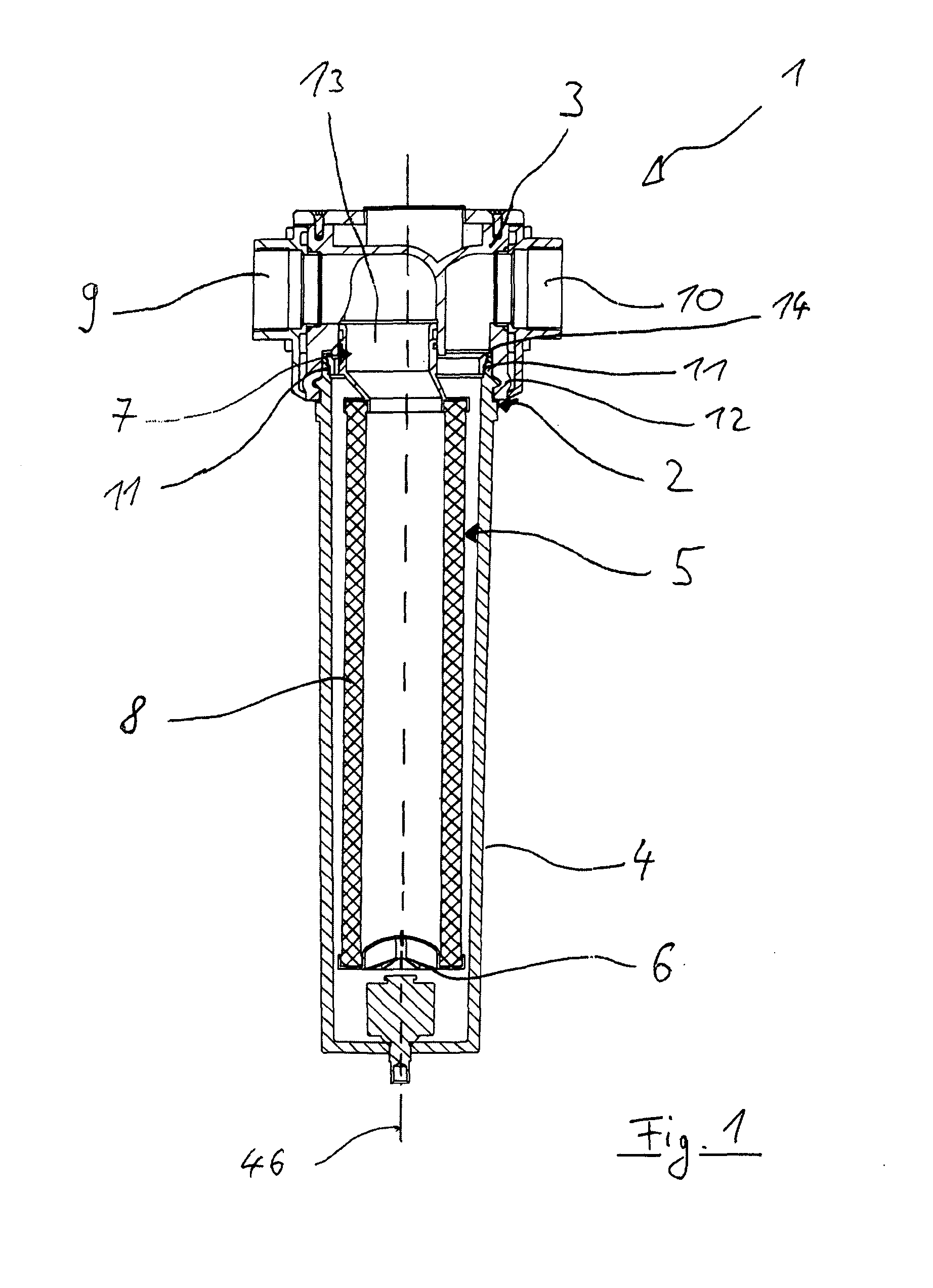
[0096]According to the present first embodiment, the rotary connection 12 between the housing cap 4 and the housing upper portion 3 is in the form of a bayonet-type connection so that the assembly of the housing cap 4 on the housing upper portion 3 is associated with a rotational movement of the housing cap 4 about the longitudinal axis thereof relative to the housing upper portion 3. However, the rotary connection 12 can also be constructed by means of a suitable threaded connection or the like.

[0097]In the first embodiment, a bayonet-type connection without any pitch is preferably used in such a manner that the closure rotation between the housing cap 4 and the housing upper portion 3 is carried out without any relative axial movement between those two components.

[0098]In order to introduce the filter element 5 into the filter housing 2, the filter element 5 is first screwed into the housing cap 4 by means of the threaded connection 11 or the inner thread 21 and the outer thread 2...

second embodiment

[0113]Similarly to the first preferred embodiment, introducing or screwing the filter element 5 into the housing cap 4 also produces further insertion of the filter element 5 into the housing cap 4 in such a manner that the second sealing face 24 radially expands the sealing ring 22 along the abutment face 16, as illustrated in FIG. 3.6, and urges it into sealing abutment with the first sealing face of the housing upper portion 3 (not illustrated).

[0114]With regard to features and operations of the present invention which have not been explained in greater detail in conjunction with the above description of the second preferred embodiment, reference may be made to the previous description of the first embodiment because those features and operations are of similar form so that it is possible to dispense with a detailed explanation thereof in order to avoid unnecessary repetition.

[0115]A compressed air filter 1 and a filter element 5 according to a third preferred embodiment of the ...

third embodiment

[0116]According to the third preferred embodiment, in comparison with the two embodiments mentioned above, a relative movement between the collar portion 14 of the filter element 5 and the housing cap 4 is brought about in a different manner during the closure movement of the filter housing 2. the rotary connection 12 between the housing upper portion 3 and the housing cap 4 is constructed as a bayonet-type connection having a predetermined pitch so that the housing upper portion 3 and the housing cap 4 carry out relative axial movement in a direction towards each other during closure movement of the filter housing 2.

[0117]A stop device 28 is also provided which produces an axial stop between the collar portion 14 of the element upper portion 7 and the housing upper portion 3 in order to axially move the element upper portion 7 and consequently the abutment face 16 of the collar portion 14 relative to the housing cap 4 during a closure movement of the filter housing 2. The stop dev...


PUM

PropertyMeasurementUnit
Angleaaaaaaaaaa
Angleaaaaaaaaaa
Forceaaaaaaaaaa

Abstract

A compressed air filter and a filter element which is for separating foreign bodies from a compressed air stream and which has an element lower portion, an element upper portion which has a neck portion which forms a first flow channel and a collar portion which is constructed so as to extend at least partially around the neck portion and which is connected to the neck portion so as to form a second flow channel, and a filter medium which is sealingly connected to the element lower portion and the element upper portion in order to form a gas flow path between the first flow channel and the second flow channel through the filter medium, the collar portion having an abutment face, which is provided at least partially at the outer periphery and which tapers in the direction of the element lower portion, in order to receive an associated sealing ring in such a manner that a force which acts substantially axially on the sealing ring from the direction of the element lower portion brings about radial expansion of the sealing ring along the abutment face.

Description

CROSS-REFERENCE TO RELATED APPLICATIONS[0001]This application is a continuation of PCT / EP2009 / 067529 filed Dec. 18, 2009 and claims the benefit of and priority to German Patent Application No. 10 2008 054 878.2, filed Dec. 18, 2008, the entire disclosure of which is herein incorporated by reference.FIELD OF THE INVENTION[0002]The present invention relates to a filter element and a compressed air filter for separating foreign bodies from a compressed air stream.[0003]Although the present invention can be used in any filter systems, the present invention and the problem addressed by it are explained in greater detail in relation to a compressed air filter. However, the notion of the present invention can also be used, for example, in a fluid separator or the like.[0004]Conventional compressed air filters generally comprise a two-piece housing having a housing upper portion and a housing cap which are either screwed together or connected to each other by means of a cap nut or bayonet-t...

Claims


Application Information

Patent Timeline
IPC IPC(8): B01D46/24
CPCB01D46/0039B01D2271/027B01D46/2414B01D46/0004
Inventor FOERSTER, ANDREASFISCHER, NORBERTFEISTHAUER, MICHAEL
Owner KAESER KOMPRESSOREN SE
Why Eureka
Try Eureka