
Muzzle loading rifle with centerfire cartridge ignition

a technology of centerfire and muzzle loader, which is applied in the field of muzzle loader, can solve the problems of difficult task and disadvantage of not being able to be used in what is normally thought of as a centerfire rifle, and achieve the effect of convenient handling and loading for operators

Inactive Publication Date: 2011-12-08
OVERSTREET JOHN L
View PDF2 Cites 13 Cited by
  • Summary
  • Abstract
  • Description
  • Claims
  • Application Information

AI Technical Summary

Benefits of technology

An advantage of the present invention is that an action of a centerfire rifle may be operated in a typical fashion to ignite the black powder charge within the primary chamber in the barrel.
is that an action of a centerfire rifle may be operated in a typical fashion to ignite the black powder charge within the primary chamber in the barrel.
Another advantage is that the centerfire casing can be configured to accept a typical primer for such a casing, or a different (e.g., hotter) primer for such casing.
Yet another advantage is that the centerfire casing is easier for an operator to handle and load than a typcial percussion cap or 209 shotgun primer by itself.

Problems solved by technology

Some users may find this task difficult to carry out.
Further, regardless of the type of muzzle loader used, all muzzle loaders to date have the disadvantage of not being able to be used in what is normally thought of as a centerfire rifle.

Method used


Image

  • Muzzle loading rifle with centerfire cartridge ignition
  • Muzzle loading rifle with centerfire cartridge ignition
  • Muzzle loading rifle with centerfire cartridge ignition

Examples


Embodiment Construction

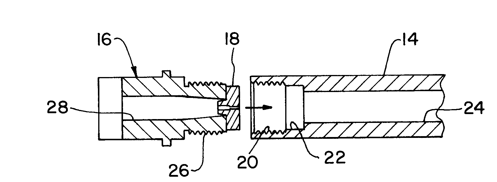
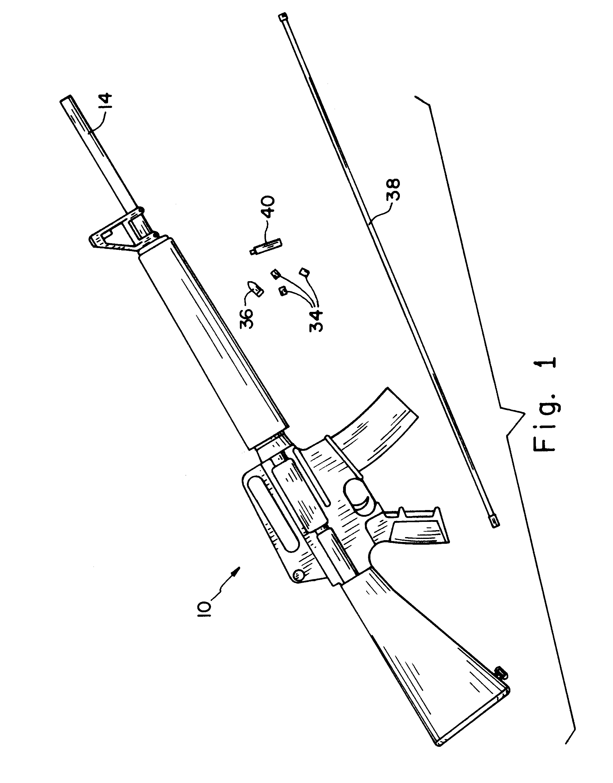
Referring now to the drawings, and more particularly to FIG. 1, there is shown an embodiment of a muzzle loading rifle 10 of the present invention. In the illustrated embodiment, muzzle loading rifle 10 is configured as an AR15 style rifle. The M16 / AR15 rifles are used worldwide by military and law enforcement organizations and civilian sport enthusiasts. M16 and AR-15 rifles are substantially the same, except that the M16 is switchable between automatic and semi-automatic operation, and the AR15 operates only in the semi-automatic mode. As a result, most of the components of M16 and AR15 rifles are substantially the same and are referred to as M16 / AR15 components.

An AR15 is generally constructed in modular “groups” allowing easy takedown and cleaning in the field. The upper receiver group generally includes the upper portion of the receiver, barrel, top rail and forestock. The lower receiver group includes the trigger assembly and pistol grip. The buttstock extends rearwardly from ...


PUM


Abstract

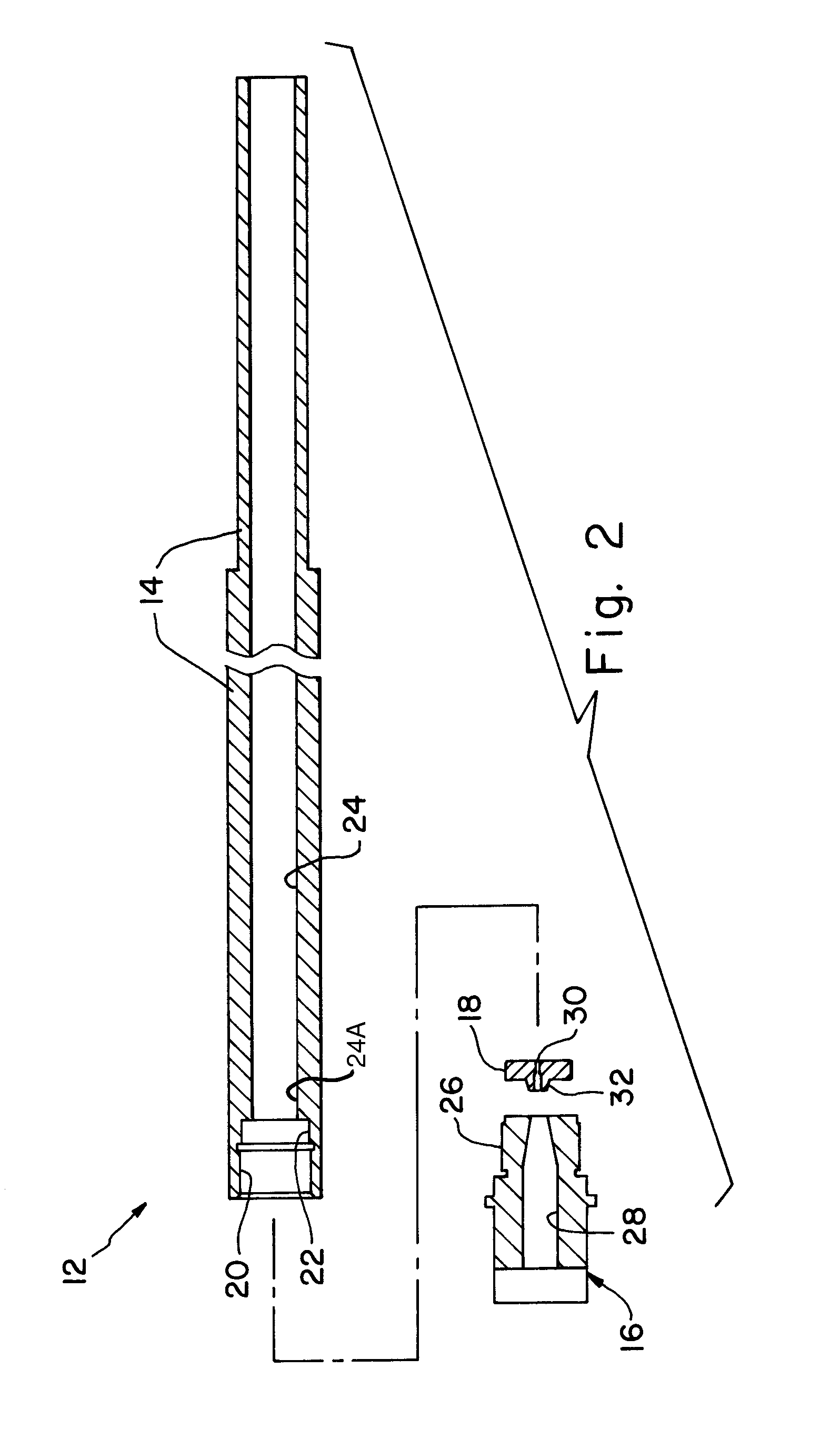
A muzzleloading rifle includes an action and a barrel assembly attached to a forward end of the action. The barrel assembly includes a barrel, a barrel extension and an intervening wall. The barrel has a breach end, a muzzle end and a primary chamber at the breach end for receiving a primary charge loaded through the muzzle end. The barrel extension is attached to the breach end of the barrel and includes a casing chamber positioned rearwardly from the primary chamber. The casing chamber is configured to receive a standard ammunition casing with an integral primer therein. The intervening wall separates the primary chamber from the casing chamber. The intervening wall includes a flash hole communicating between the casing chamber and the primary chamber.

Description

BACKGROUND OF THE INVENTION1. Field of the InventionThe present invention relates to muzzle loading rifles, and, more particularly, to ignition systems for muzzleloading rifles.2. Description of the Related ArtMuzzle loading rifles were the first type of firearms used by humans. Historically, such rifles can be categorized by the particular type of ignition system used to ignite the black powder propellant. First were wheel lock rifles, followed by flintlock rifles, then percussion rifles, and more recently, inline rifles.Wheel lock rifles were first used in China and have a rotating lock carrying a fuse which passes through a hole in the barrel and ignites the black powder. Flintlock rifles use a piece of flint stone carried at the end of a rotating hammer to ignite a powder charge in a striker pan, which in turn sends a flame through a flash hole to the primary black powder charge in the barrel. Percussion rifles are similar in design, except that the hammer ignites a percussion c...

Claims


Application Information

Patent Timeline
Patent Type & Authority Applications(United States)
IPC IPC(8): F41C9/08
CPCF41C9/08
Inventor OVERSTREET, JOHN L.
Owner OVERSTREET JOHN L
Learn More