Orthodontic appliance with encoded information formed in the base

Inactive Publication Date: 2011-11-24
RMO INC
View PDF3 Cites 40 Cited by
  • Summary
  • Abstract
  • Description
  • Claims
  • Application Information

AI Technical Summary

Benefits of technology

[0012]Also, note that the cylindrical recess may include additional features or mechanisms that prevent the rotatable member from freely rotating within the cylindrical recess. In one or more embodiments, a circular cross section (perpendicular to the central axis of the cylindrical recess) may be slightly out of round in various places to frictionally engage adjacent surfaces of the rotatable member for assisting in maintaining the slot coverable extensions in one or more predetermined orientations relative to the slot. In one or more embodiments of the bracket, the cylindrical recess and the rotatable member may include interlocking elements that substantially restrict the rotation of the rotatable member to discrete and predetermined angular orientations about the central axis. Such interlocking elements may provide a ratchet mechanism, or alternatively interlocking shapes wherein a first shaped element (e.g., on the cylindrical portion of the rotatable member or a wall portion of the cylindrical recess) mates or interlocks with compatibly one or more shaped elements (on the other of the rotatable member or a wall of the cylindrical recess) dispersed at discrete angular positions about the central axis for restricting rotation of the rotatable member from one of these positions to another. Note that such interlocking elements may allow the rotatable member to rotate in both a clockwise and a counter clockwise direction when a sufficient predetermined directional force(s) is applied for disengaging the interlocking elements from a first position and interlocking at a second position.
[0046]In some embodiments, a range of adjustability is provided in the range of motion of a closing or locking member, thus limiting the forces encountered by an archwire held in the archwire slot, thus permitted desired sliding of the archwire in the slot. To accomplish this end, a camming mechanism can be employed. The bracket body may be formed from a non-metallic material, such as a polymer, a filled polymer composite, or a ceramic, and the self-ligating mechanism may be formed from a metal. A resilient engagement member with a detent positioned to engage an aperture can be employed to achieve secure closure.

Problems solved by technology

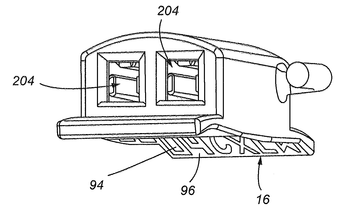
However, the '494 Patent and the other patents noted above fail to disclose a base structure that includes lettering, symbols, or numerals that are substantially continuous and that functionally serve as texturing to enhance the adhesive bonding surface of, e.g., an orthodontic appliance to a patient's tooth.
In particular, such extensions, when rotated to occlude at least a portion of the slot opening thereby preventing an archwire residing in the bracket slot from exiting therefrom, and when rotated out of the slot opening, these extensions do not prevent the archwire from being readily removed from the bracket slot, e.g., by an orthodontist or technician.
In particular, in the passive archwire restraining configuration, there is insufficient frictional forces between the archwire and the slot (for orthodontic purposes) to effectively inhibit movement of the archwire in a direction along the length of the slot.

Method used


Image

  • Orthodontic appliance with encoded information formed in the base
  • Orthodontic appliance with encoded information formed in the base
  • Orthodontic appliance with encoded information formed in the base

Examples


Embodiment Construction

[0118]In the various embodiments of orthodontic brackets, and components thereof described hereinbelow, different embodiments of features or elements having a same general functionality will typically be identified by a label having a same numical portion of the label, but a different letter as a suffix. Thus, for example, various embodiments of a self ligating orthodontic bracket are disclosed hereinbelow, and identified by the numerical label “404”, but at least some of these different embodiments are distinguished from one another by different letters such that different bracket embodiments are identified below as “404”, “404a”, “404b”, etc.

[0119]A self-ligating orthodontic bracket 404 is shown in FIG. 42 having a bracket body 408 with a back 412 and a front surface 416. The bracket body 408 has a left side 420 and right side 424. An archwire slot 428 that has a length generally spanning the extent between the left side 420 to the right side 424 in the front surface 416. Attached...


PUM


Abstract

The present disclosure is directed, at least in part, to a self ligating orthodontic bracket having a rotatable member for securing an archwire within a slot of the bracket. Embodiments of the orthodontic bracket disclosed herein include a bracket body containing the archwire slot as well as tie wings for attaching various orthodontic devices (e.g., elastomeric bands) to the bracket. The rotatable member is rotatable in a first direction (e.g., counter clockwise) relative to a body of the bracket for securing or locking the archwire within the slot, and for rotating in an opposite direction (e.g., a clockwise direction) relative to the bracket body for unsecuring or unlocking the archwire so that it is substantially unrestrained from exiting the slot.

Description

REFERENCE TO RELATED APPLICATIONS[0001]The present application is a continuation-in-part of U.S. patent application Ser. No. 11 / 782,569, filed Jul. 24, 2007, which is a continuation-in-part of U.S. patent application Ser. No. 10 / 848,929, filed May 18, 2004, now U.S. Pat. No. 7,247,018, which is a continuation-in-part of U.S. patent application Ser. No. 10 / 284,016, filed on Oct. 29, 2002, now U.S. Pat. No. 6,846,178; the present application is also a continuation-in-part of U.S. patent application Ser. No. 12 / 758,090, filed Apr. 12, 2010, which is a continuation of U.S. patent application Ser. No. 11 / 260,923, filed Oct. 27, 2005, now U.S. Pat. No. 7,695,277, which claims the benefit of U.S. Provisional Application No. 60 / 623,715, filed on Oct. 28, 2004; the present application also claims the benefit of U.S. Provisional Patent Application No. 61 / 518,927, filed on May 12, 2011; each of the above-identified applications are incorporated fully herein by reference.FIELD OF THE INVENTION[...

Claims


Application Information

Patent Timeline
IPC IPC(8): A61C7/28
CPCA61C7/143A61C7/285A61C7/28A61C7/16A61C7/30
Inventor DUPRAY, DENNIS J.SMITH, JEFFREY ALLENTRINH, NAMZAKHEM, TONYUPCHURCH, DAPHNE
Owner RMO INC
Why Eureka
Try Eureka