
Linearization systems and methods for variable attenuators

a linearization system and variable attenuator technology, applied in the field of variable gain attenuators, can solve problems such as degrading the gain linearity, and achieve the effect of improving the gain linearity of the variable attenuator and alleviating the variation of the channel resistance of the connected transistor

Active Publication Date: 2011-11-24
SAMSUNG ELECTRO MECHANICS CO LTD +1
View PDF3 Cites 20 Cited by
  • Summary
  • Abstract
  • Description
  • Claims
  • Application Information

AI Technical Summary

Benefits of technology

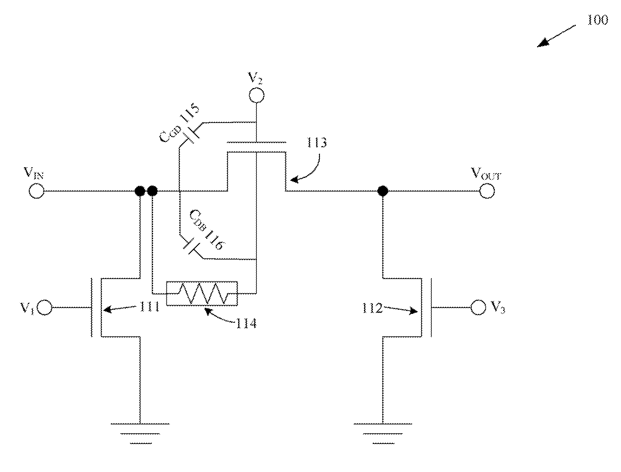
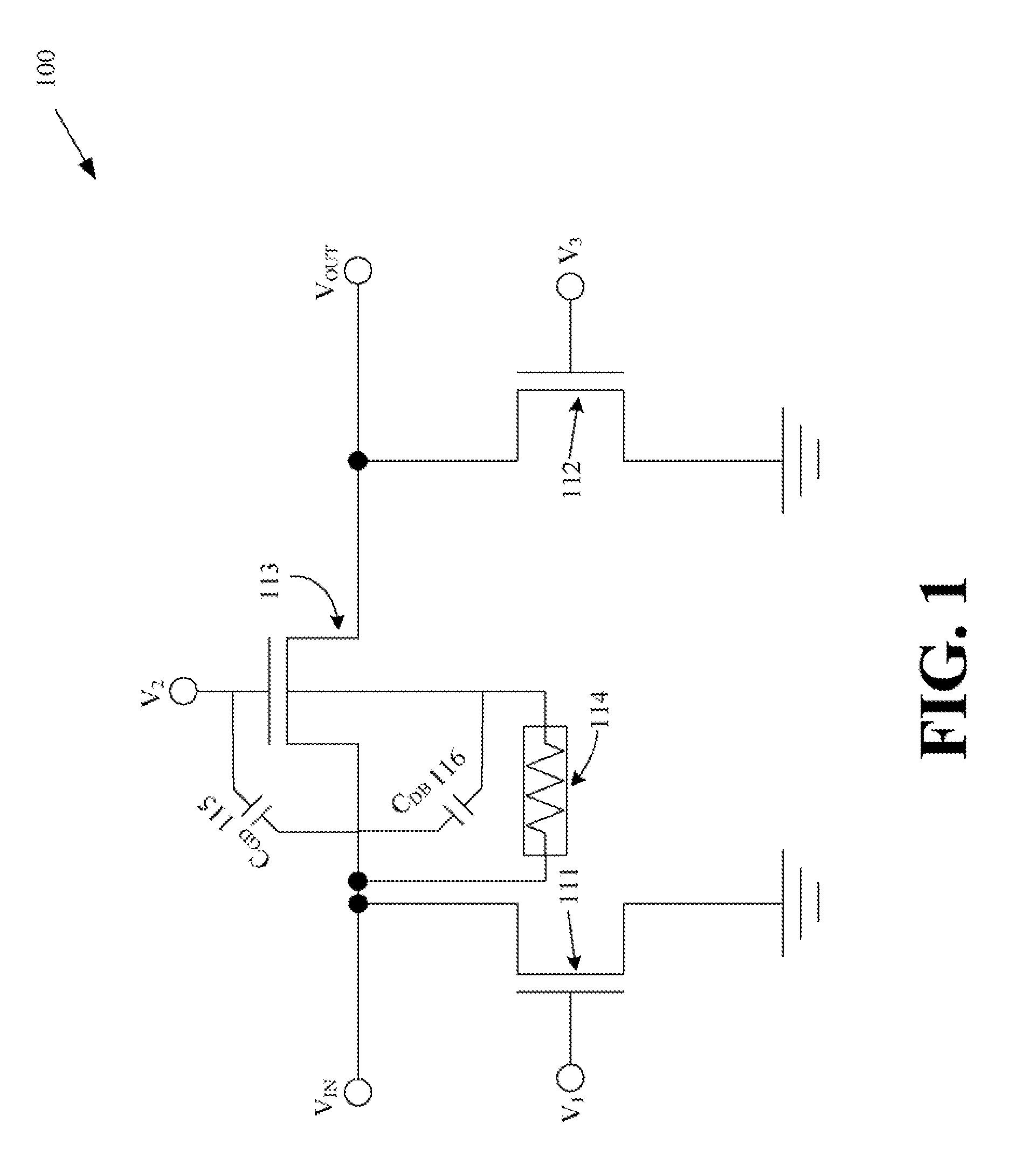
[0007]Example embodiments of the invention may provide an example bootstrapping body bias for one or a plurality of transistors in a variable attenuator. The transistors may be metal-oxide-semiconductor field-effect transistor (MOSFETs). In accordance with an example bootstrapping body bias, the channel resistance variation of a connected transistor may be alleviated by manipulating the body effect, and the gain linearity of the variable attenuator may be improved.

Problems solved by technology

However, the impedance of a MOSFET varies significantly with the strength of input signals it carries, thereby degrade its gain linearity.

Method used


Image

  • Linearization systems and methods for variable attenuators
  • Linearization systems and methods for variable attenuators
  • Linearization systems and methods for variable attenuators

Examples


Embodiment Construction

[0017]Example embodiments of the invention will now be described more fully hereinafter with reference to the accompanying drawings, in which some, but not all embodiments of the invention are shown. Indeed, these inventions may be embodied in many different forms and should not be construed as limited to the embodiments set forth herein; rather, these embodiments are provided so that this disclosure will satisfy applicable legal requirements. Like numbers refer to like elements throughout.

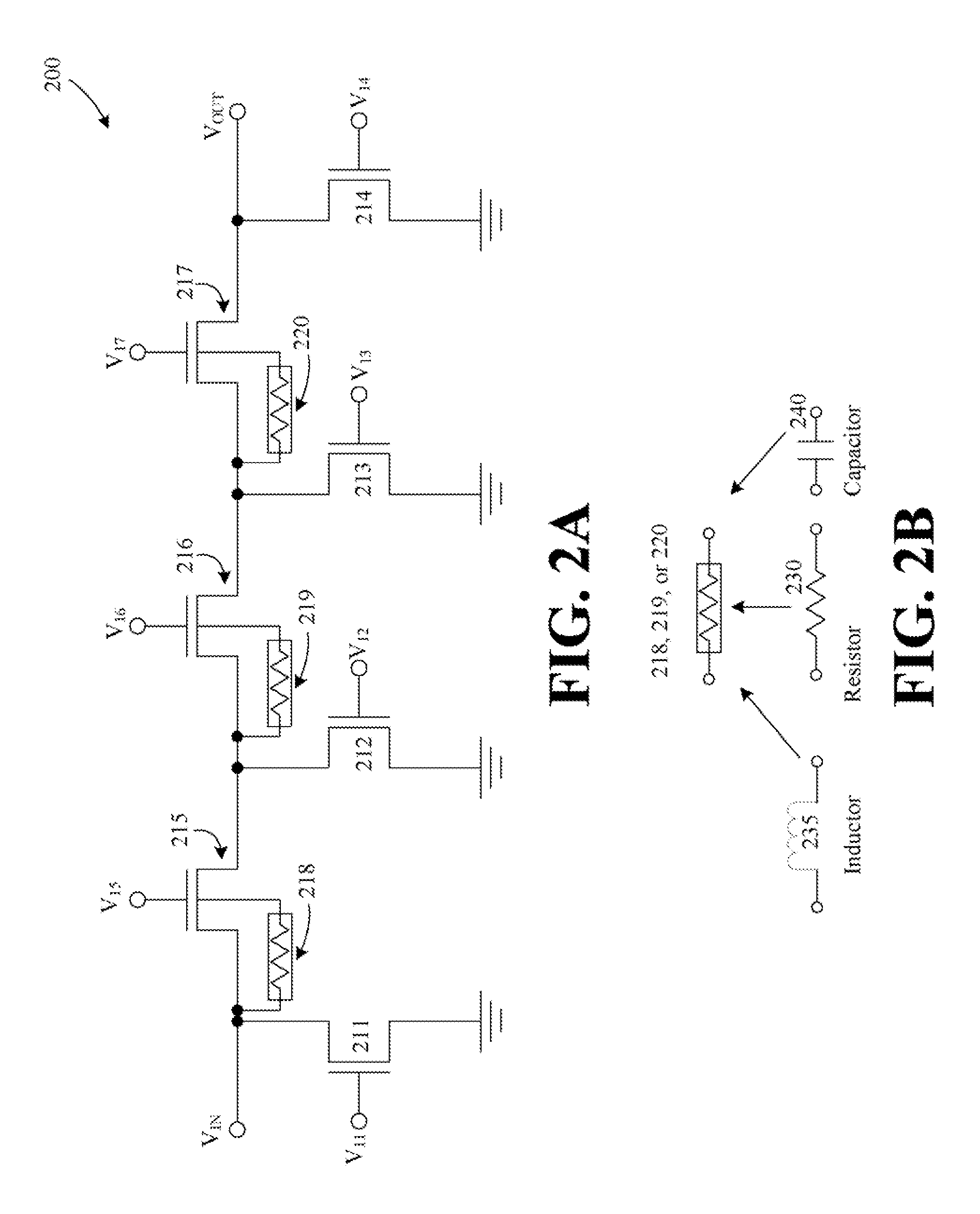
[0018]Embodiments of the invention may be directed to variable attenuators using one or more series transistors and shunt transistors to provide variable impedances. These transistors can include MOSFETs, according to an example embodiment of the invention. Additionally, bootstrapping body bias circuits can be provided for one or more of the series transistors in the series path from the input to output of the variable attenuator to alleviate the channel resistance variation of a series transistor...


PUM


Abstract

Systems and methods for provided for linearization systems and methods for variable attenuators. The variable attenuators can include series transistors along a main signal path from the input to output, as well as shunt transistors. A bootstrapping body bias circuit can be used with one or of the series transistors to allow the body of a connected transistor to swing responsive to a received RF input signal. As the RF signal increases and affects the gate-to-source voltage difference of a transistor, a bootstrapping body bias circuit can adaptively adjust the threshold voltage of the connected transistor and compensate the channel resistance variation resulting from gate-to-source voltage swing. The bootstrapping body bias circuit can be implemented using passive elements, active elements, or a combination thereof.

Description

FIELD OF THE INVENTION[0001]Embodiments of the invention relates to generally to variable gain attenuators, and more specifically to variable gain attenuators utilizing transistors and bootstrapping body bias circuits to support higher power handling capabilities.BACKGROUND OF THE INVENTION[0002]Signal strength control of a system usually requires a variable gain / attenuation element. A variable attenuator is desirable in situations that need to handle higher amount of power.[0003]Passive elements in an variable attenuator may grouped into two kinds—(i) one includes series elements that connect parallel to the direction of the input terminal to output terminal, and (ii) the second includes shunt elements that connect from the input, the output, or the intersection points of two series elements to the ground (earth).[0004]An attenuator may have lower attenuation when its series elements have smaller impedance and its shunt elements have higher impedance. At such a setting, the input s...

Claims


Application Information

Patent Timeline
Patent Type & Authority Applications(United States)
IPC IPC(8): H01P1/22
CPCH01P1/22H03H11/245H03G1/007
Inventor HUANG, YANYUWOO, WANGMYONGLEE, CHANG-HOLASKAR, JOY
Owner SAMSUNG ELECTRO MECHANICS CO LTD
Learn More