Multi-Level Transmitter Circuit Having Substantially Constant Impedance Output
a transmitter circuit and substantially constant technology, applied in the field of multi-level (five level) transmitter circuit 10, to achieve the effect of constant output impedan
- Summary
- Abstract
- Description
- Claims
- Application Information
AI Technical Summary
Benefits of technology
Problems solved by technology
Method used
Image
Examples
Embodiment Construction
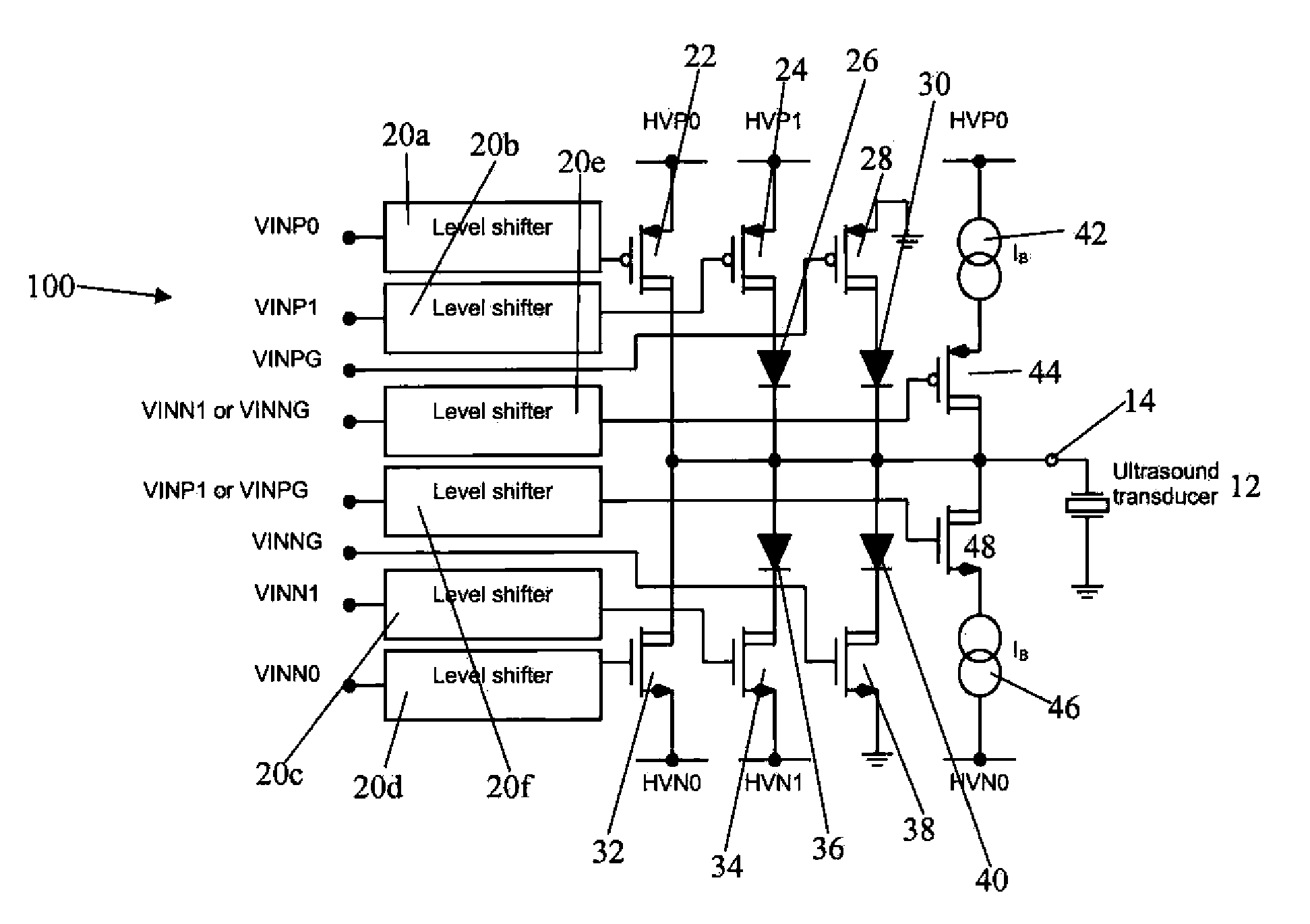
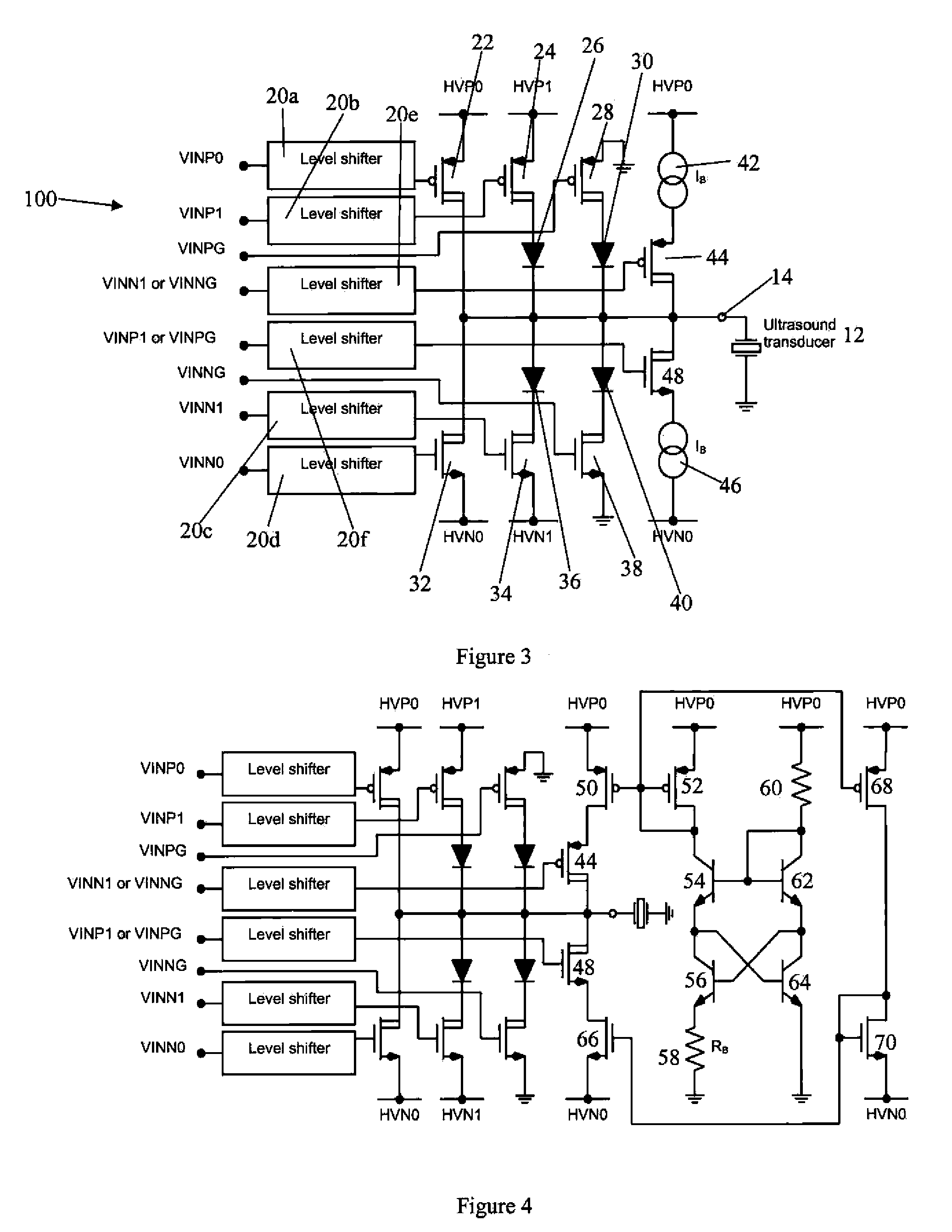
[0014]Referring to FIG. 3 there is shown a circuit diagram of a multi-level transmitter circuit 100 of the present invention. The circuit 100 is similar to the circuit 10 shown in FIG. 1a, and same numerals will be used for same parts.
[0015]The circuit 100 has a first voltage path that extends from a positive voltage source HVP0 through a PMOS transistor 22 to the output node 14. The transistor 22 is activated by the signal from the output of the voltage level shifter 20a, whose input is the input signal VINP0. The circuit 100 has a second voltage path that extends from a positive voltage source HVP1 through a PMOS transistor 24 through a diode 26 to the output node 14. The voltage HVP1 is less positive than the voltage HVP0. The transistor 24 is activated by the signal from the output of the voltage level shifter 20b, whose input is the input signal VINP1. The circuit 100 has a third voltage path that extends from ground through a PMOS transistor 28 through a diode 30 to the output...
PUM
 Abstract
Description
Claims
Application Information
 - R&D
- Intellectual Property
- Life Sciences
- Materials
- Tech Scout
- Unparalleled Data Quality
- Higher Quality Content
- 60% Fewer Hallucinations
Browse by: Latest US Patents, China's latest patents, Technical Efficacy Thesaurus, Application Domain, Technology Topic, Popular Technical Reports.
© 2025 PatSnap. All rights reserved.Legal|Privacy policy|Modern Slavery Act Transparency Statement|Sitemap|About US| Contact US: help@patsnap.com


