Systems and methods for regulating fuel cell air flow during low loads or cold temperature operation

a fuel cell and air flow technology, applied in the field of thermal management systems and methods, can solve the problems of fuel cell air flow, fuel cell may not efficiently produce electrical output, and fuel cell stack undercooling, etc., and achieve the effect of increasing the resistance to thermal management fluid flow

Active Publication Date: 2011-11-17
DCNS SA
View PDF6 Cites 17 Cited by
  • Summary
  • Abstract
  • Description
  • Claims
  • Application Information

AI Technical Summary

Benefits of technology

[0010]The present disclosure is directed to systems and methods for regulating fuel cell air flow, such as during low loads and / or cold temperature operation. These systems and methods may include providing a thermal management fluid to the fuel cell stack, transferring thermal energy between the thermal management fluid and the fuel cell stack, and / or varying the flow rate of the thermal management fluid that comes into thermal contact with the fuel cell stack to maintain the temperature of the fuel cell stack within a desired temperature range. Varying the flow rate of the thermal management fluid may include varying the overall supply rate of the thermal management fluid within the fuel cell system and / or providing an alternative flow path for the thermal management fluid such that a portion of the thermal management fluid supplied by the fuel cell system does not come into thermal contact with the fuel cell stack. In some embodiments, varying the overall supply rate of the thermal management fluid within the fuel cell system may include varying the rotational frequency of an air drive assembly, such as a fan assembly. In some embodiments, varying the overall supply rate of the thermal management fluid within the fuel cell system may include partially or completely occluding a flow path for the thermal management fluid, thus increasing a resistance to thermal management fluid flow within the fuel cell system. In some embodiments, providing an alternative flow path for the thermal management fluid may include selectively diverting a portion of the thermal management fluid stream such that it does not come into thermal contact with the fuel cell stack. In some embodiments, the selectively diverting and / or the selective occluding may include a passive flow-regulating device that is configured to modify (or otherwise adjust or regulate) the flow rate of the thermal management fluid therethrough based at least in part on a variable associated with the thermal management fluid. In some embodiments, the variable associated with the thermal management fluid includes the pressure drop of the thermal management fluid across the flow-regulating device. In some embodiments, the regulating and / or varying of the flow rate of the thermal management fluid is automatic and / or without positive (active and / or computerized) control.

Problems solved by technology

If the membrane is below this range of suitable operating temperatures, the fuel cell may not efficiently produce its electrical output.
On the other hand, if the membrane is above this range of suitable temperatures, degradation of the membrane may occur.
If the thermal management system is unable to provide this broad range of thermal management fluid flow rates, overcooling and / or undercooling of the fuel cell stack may result.
Overcooling may cause the temperature of the fuel cell stack to decrease below an acceptable level, resulting in a decrease in fuel cell stack reaction kinetics and / or condensation of liquid water within the fuel cell stack, which may cause flooding of the fuel cell stack.
Undercooling may cause the temperature of the fuel cell stack to increase to above an acceptable level, resulting in dehydration of the electrolytic membrane within the fuel cell stack, decreased reactant diffusion through the electrolytic membrane, and / or irreversible damage to fuel cell stack components.
It may be difficult to obtain this broad range of thermal management fluid flow rates without the use of complicated control systems and methods and / or multiple cooling devices.

Method used


Image

  • Systems and methods for regulating fuel cell air flow during low loads or cold temperature operation
  • Systems and methods for regulating fuel cell air flow during low loads or cold temperature operation
  • Systems and methods for regulating fuel cell air flow during low loads or cold temperature operation

Examples


Embodiment Construction

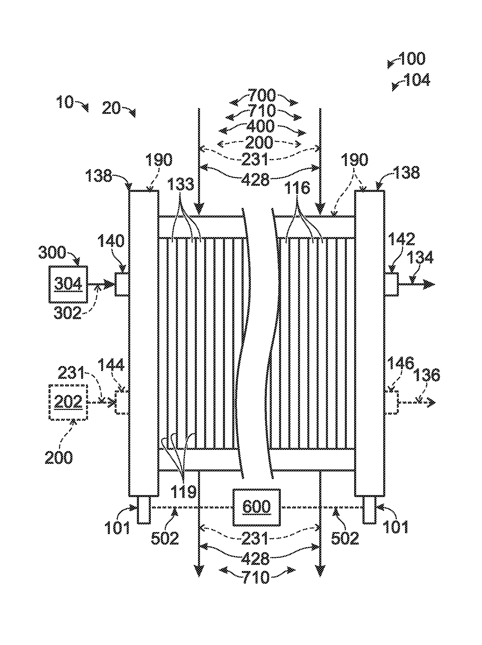
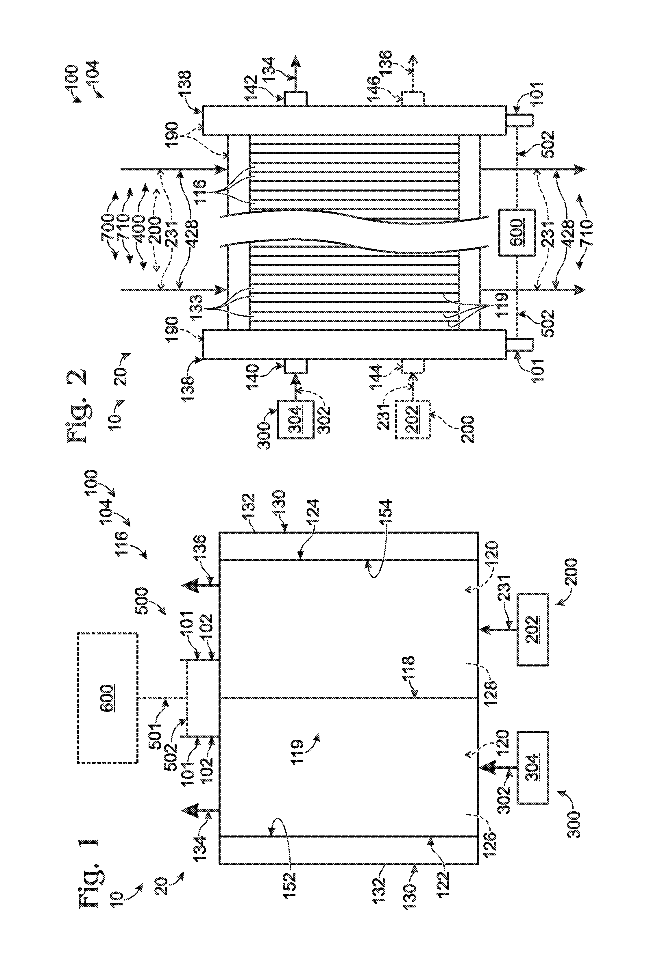
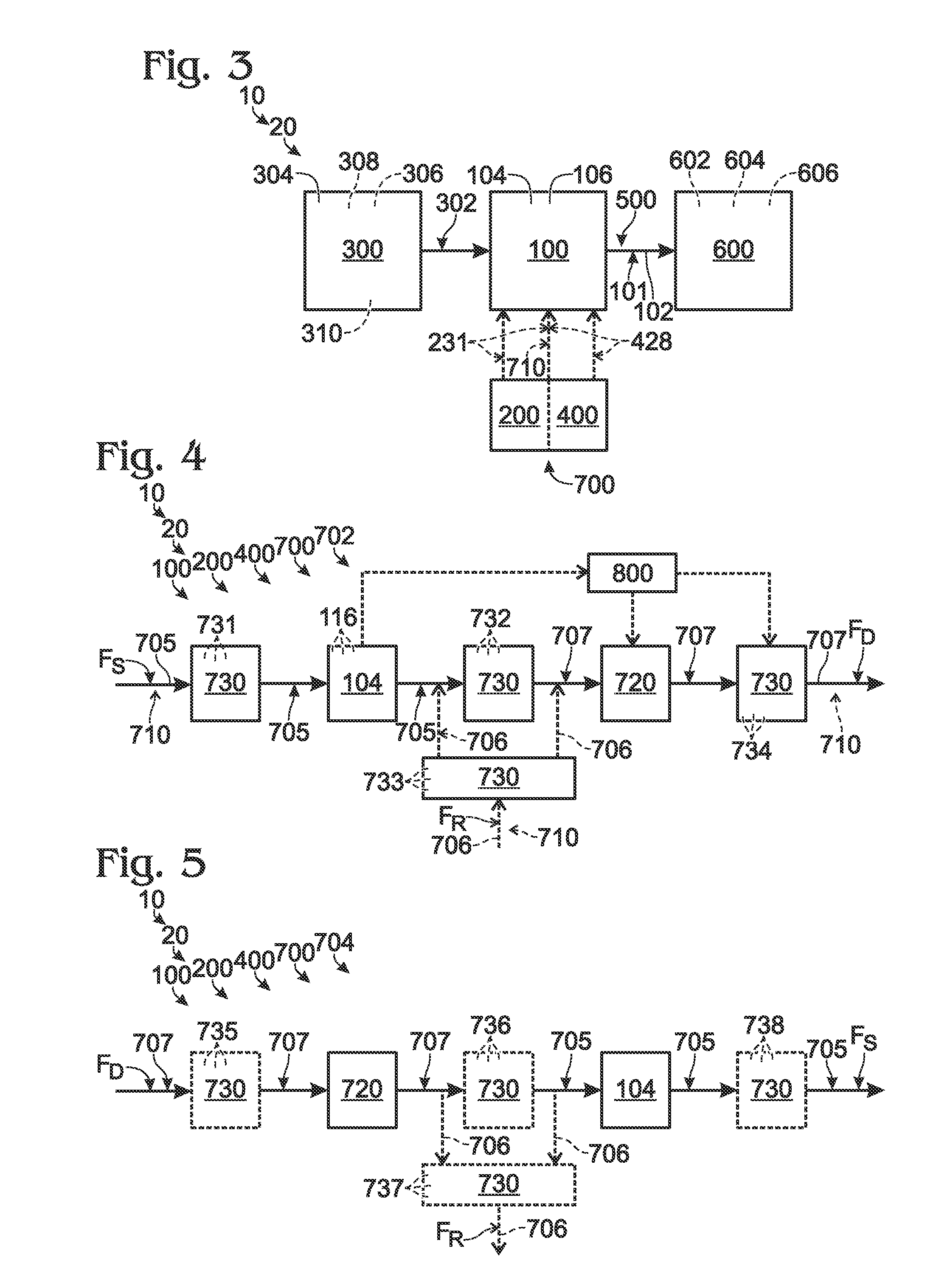
[0025]The present disclosure is directed to systems and methods for regulating the temperature of a fuel cell during low load and / or cold temperature operation. As discussed in more detail herein, these systems and methods may include providing a thermal management fluid to the fuel cell stack, transferring thermal energy between the thermal management fluid and the fuel cell stack, and varying the flow rate of the thermal management fluid that comes into thermal contact with the fuel cell stack to maintain the fuel cell stack within an acceptable temperature range. Varying the flow rate of the thermal management fluid that comes into contact with the fuel cell stack may include varying the overall supply rate of the thermal management fluid within the fuel cell system and / or providing an alternative flow path for the thermal management fluid within the fuel cell system such that a portion of the thermal management fluid supplied by the fuel cell system does not come into thermal co...


PUM


Abstract

Systems and methods for regulating fuel cell air flow, such as during low loads and / or cold temperature operation. These systems and methods may include providing a thermal management fluid, such as air, to the fuel cell stack, transferring thermal energy between the thermal management fluid and the fuel cell stack, and varying the flow rate of the thermal management fluid that comes into contact with the fuel cell stack to maintain the temperature of the fuel cell stack within an acceptable temperature range. Varying the flow rate of the thermal management fluid may include varying the overall supply rate of the thermal management fluid within the fuel cell system and / or providing an alternative flow path for the thermal management fluid such that a portion of the thermal management fluid supplied by the fuel cell system does not come into contact with the fuel cell stack.

Description

RELATED APPLICATIONS[0001]The present application claims priority to similarly entitled U.S. Provisional Patent Application Ser. No. 61 / 333,350, which was filed on May 11, 2010, and the complete disclosure of which is hereby incorporated by reference.FIELD OF THE DISCLOSURE [0002]The present disclosure is related generally to thermal management systems and methods, and more specifically to systems and methods for thermal management of fuel cell systems under low load or low ambient temperature conditions.BACKGROUND OF THE DISCLOSURE [0003]Fuel cell stacks are electrochemical devices that produce water and an electrical potential from a fuel, such as a proton source, and an oxidant. Although other fuels and oxidants may and have been used, many conventional fuel cell stacks utilize hydrogen gas as the proton source and oxygen gas, air, or oxygen-enriched air as the oxidant. Fuel cell stacks typically include many fuel cells that are fluidly and electrically coupled together between c...

Claims


Application Information

Patent Timeline
IPC IPC(8): H01M8/04
CPCH01M8/04014H01M8/04701Y02E60/50H01M2008/1095Y02P70/50
Inventor SKINKLE, DAVID W.
Owner DCNS SA
Why Eureka
Try Eureka