
Wedge positioning apparatus for jet pump assemblies in nuclear reactors

a technology of positioning apparatus and jet pump, which is applied in nuclear engineering, nuclear elements, greenhouse gas reduction, etc., can solve the problems of complex structure, probable cost, vibration of jet pump assemblies, etc., and achieve the effect of preventing excessive circumferential movement, preventing circumferential auxiliary wedge movement, and adding stability

Active Publication Date: 2011-11-17
WESTINGHOUSE ELECTRIC CORP
View PDF0 Cites 7 Cited by
  • Summary
  • Abstract
  • Description
  • Claims
  • Application Information

AI Technical Summary

Benefits of technology

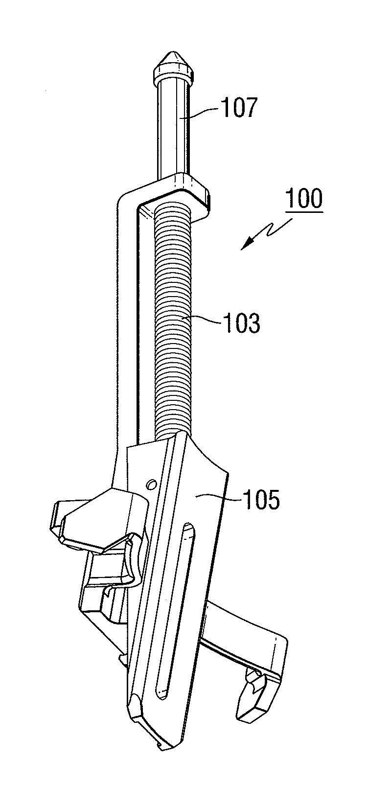
[0020](d) a single spring disposed around the slide rod, the spring contacting the top end flat portion and exerting pressure against the end flat portion of the triangular slide wedge, this pressure on the slide wedge forcing it against the jet pump assembly.Here, the at least one of the adjustment set screw blocks are positioned to contact part of the wing of the bracket body and the at least two separate auxiliary wedge positioning apparatus utilizes a combination of spring force and gravity to provide continuous adjustment against the at least one jet pump assembly. The hooked protrusions, in the form of a “gull wing,” provide stability under jet pump assembly vibration and prevent excessive circumferential movement around the jet pump assembly. The term “gull wing” is herein meant to define the configuration shown particularly in FIGS. 6 and 7 as members 150, which is a “parallel” member section, parallel and outward from the rail 110 and transverse at its bottom of the rail 110 and attached to the transverse rail 110 as shown in FIGS. 5-7; 152, which is an angled upward member; and 156, which is an angled downward member attached to 152; all of hooked protrusions 111.
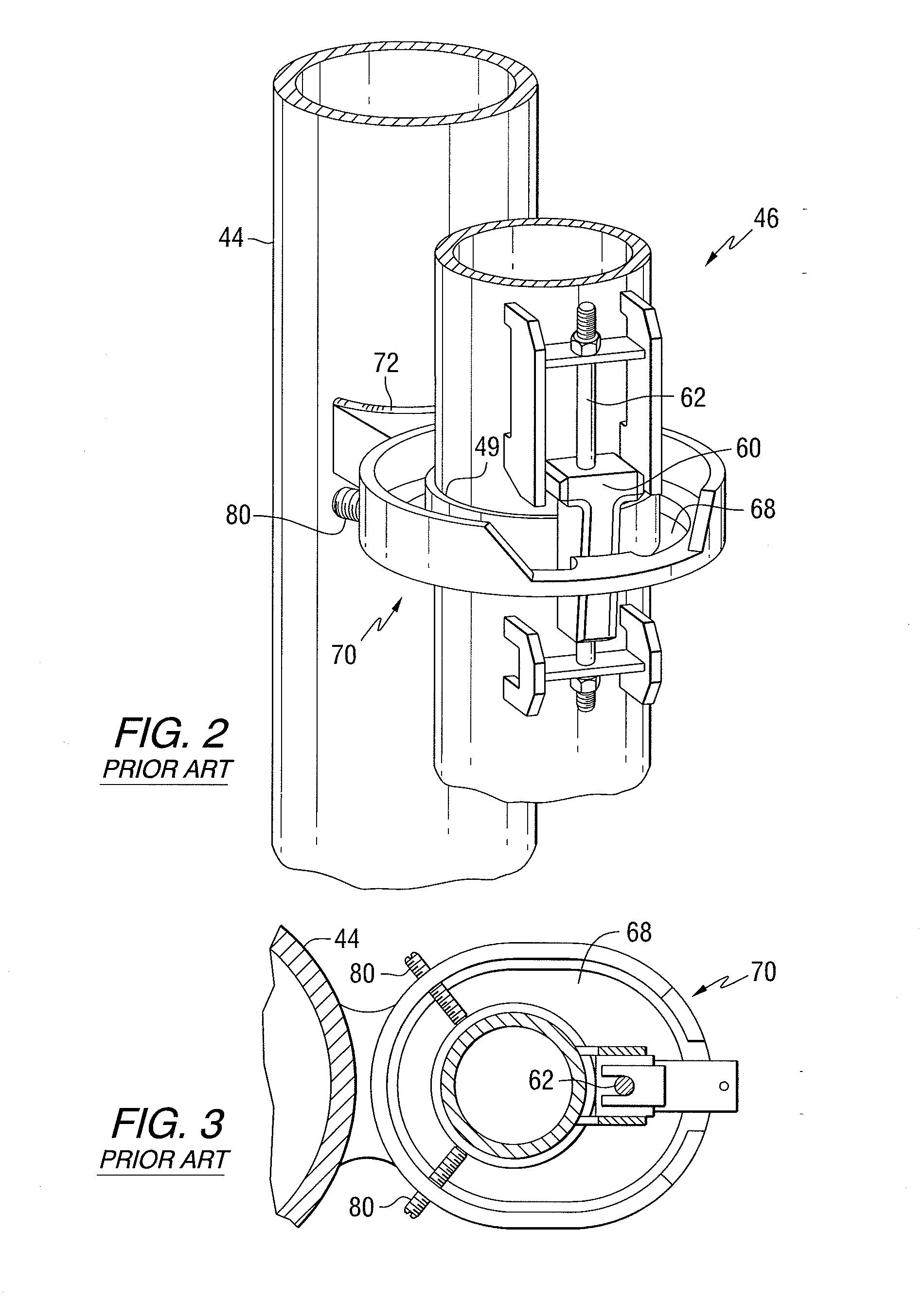
[0021]To reiterate, the auxiliary wedge of this invention uses a wedge action to restore the contact support between the jet pump restrainer bracket and the jet pump mixer (see FIG. 2). The wedge uses a combination of spring force and gravity to provide continuous adjustments for possible alignment variations of the mixer and compensations for possible settlement after installation. The lines of contact between the wedge assembly, the inlet mixer and the restrainer bracket form a triangle that adds stability when installed (see FIG. 4). Hooked protrusions, such as member 152, and wing stabilizing attachment / contact pad 155, contact or are adjacent to the set screw block 122′ (see FIG. 6) to prevent excessive circumferential movement around the mixer. These protrusions also aid in installation of the apparatus while the mixer is in place and help maintain vertical orientation under vibration conditions. The wing stabilizing attachment is parallel to the upward member and the downward member (best shown in FIG. 6) and adjacent to the at least one set screw block; and assists in preventing circumferential auxiliary wedge movement. Thus, positioning of the stabilizing attachment in such a manner is very important to this invention. The triangle contact design allows for wedge stability while not requiring machining or measurements as do other designs. The maximized stroke enables a minimum number of apparatus to accommodate the range of gap distances for the variations in existing plants.

Problems solved by technology

The jet pump assemblies are subject to vibrations caused by hydraulic forces due to the flow of water.
Problems associated with this design are complexity and probable cost.

Method used


Image

  • Wedge positioning apparatus for jet pump assemblies in nuclear reactors
  • Wedge positioning apparatus for jet pump assemblies in nuclear reactors
  • Wedge positioning apparatus for jet pump assemblies in nuclear reactors

Examples


Embodiment Construction

[0034]The present invention generally relates to an auxiliary wedge spring apparatus structured to impart a wedge action to fill the space between the jet pump restrainer bracket and the mixing section of the jet pump assembly.

[0035]Referring now to the drawings, FIGS. 4 and 5 are perspective and exploded views of an auxiliary wedge positioning apparatus 100 according to the main embodiment of the present invention. The auxiliary wedge positioning apparatus 100 includes a restraint bracket body 102, single spring 103, capture rod 104, slide wedge 105, pin 106, and single slide rod 107. As best seen in FIG. 5, the restraint bracket body 102 generally includes a rail 110 transverse to top end flat (spring stop) portion 108 angled at substantially 90° from rail 110 at a first end 116. The auxiliary hooked protrusions 111 having a “gull wing” shape, defined previously, (best shown in FIGS. 5, 6 and 7) at a second end opposite first end 116. Thus, the top of the bracket body 102 is an L ...


PUM


Abstract

An auxiliary wedge positioning apparatus / assembly 100 for use in a nuclear reactor pressure vessel 12 having riser piping 44 and 144 and a jet pump assembly 46 and 120, the apparatus 100 having a combination slide wedge 105 and spring 103 mounted on a restraint bracket body 102 having a transverse rail 110 with end gull-wing hooked protrusions 111 with sections 150, 152, 156 and wing stability attachment 155, the slide wedge used for placement between the riser piping 44 and 144 and jet pump assembly 46 and 120 to control vibrations during operation of the reactor vessel 12.

Description

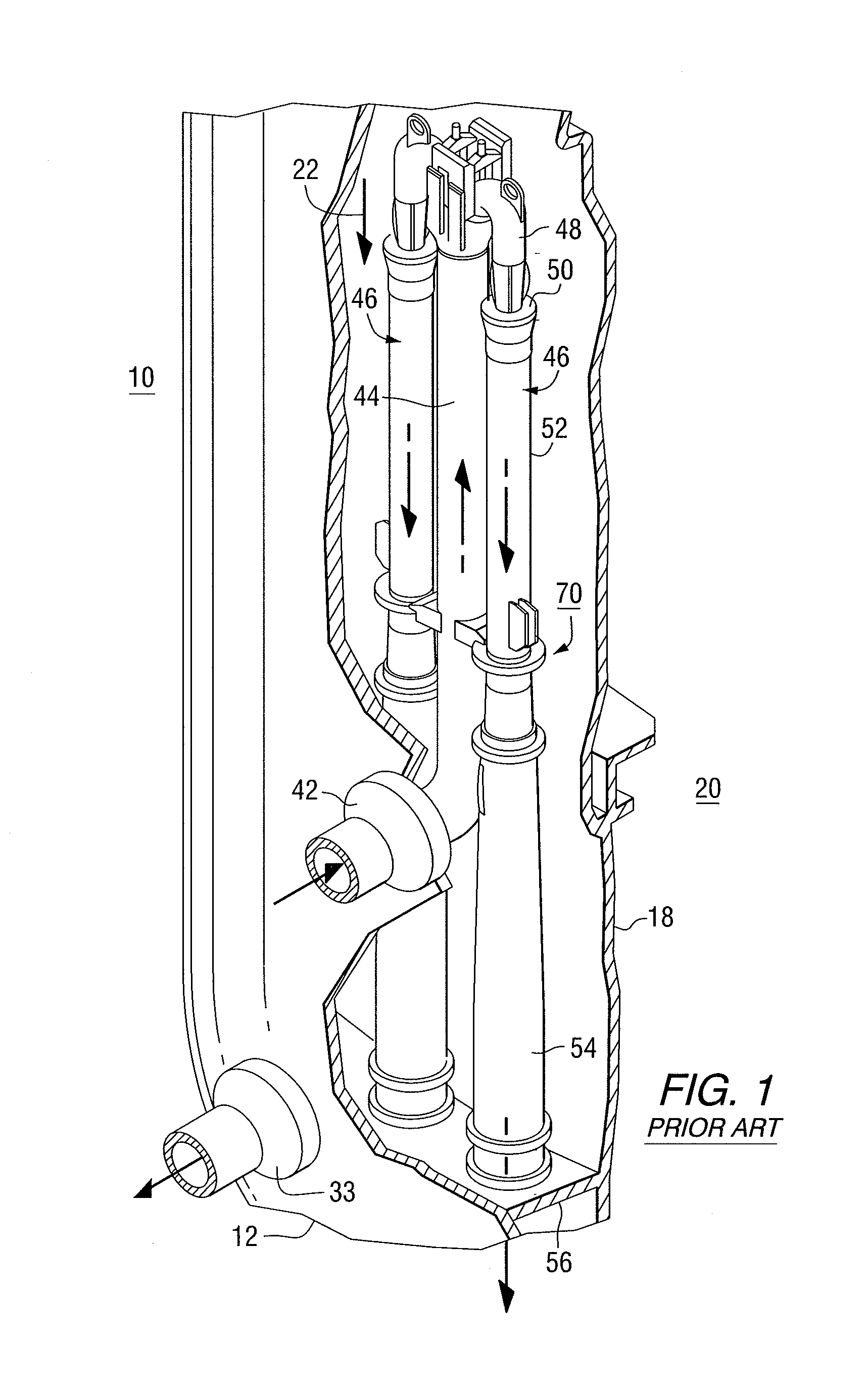
CROSS REFERENCE TO RELATED APPLICATION[0001]This application claims the benefit of U.S. Provisional Application Ser. No. 61 / 259,291, filed on Nov. 9, 2009.BACKGROUND OF THE INVENTION[0002]1. Field of the Invention[0003]This invention relates generally to jet pump stabilization in nuclear reactors and, more particularly, to an auxiliary wedge apparatus, for modifying jet pump wedge positioning assemblies within a nuclear reactor pressure vessel.[0004]2. Description of Related Art[0005]As detailed by Wivagg in U.S. Pat. No. 7,023,949 (“Wivagg '949”). Boiling water reactors (“BWRs”) are designed to generate steam in reactor pressure vessels (“RPVs”) by heating the water surrounding uranium-containing tubes of fuel assemblies located in the RPV core regions. The RPVs have recirculation loops designed to facilitate the circulation of water in the core regions. The recirculation loops pump water out of the RPVs and return the water to the inlets of jet pump assemblies located in annular r...

Claims


Application Information

Patent Timeline
IPC IPC(8): G21C19/28
CPCG21C13/032Y02E30/40G21C15/25Y02E30/30G21C19/00
Inventor FLANIGAN, MICHAEL A.KAYLOR, STEPHEN J.DUBAY, JAMES M.LUM, RODNEY
Owner WESTINGHOUSE ELECTRIC CORP
Learn More