Handlebar grip

a technology for gripping and handlebars, applied in the field of grips, can solve the problems of sleeve being subject to torsional deformation or twisting, difficult and time-consuming to mount and remove such grips, and reducing the width of the slot of the clamping devi

Inactive Publication Date: 2011-11-17
YU TSAI YUN
View PDF8 Cites 15 Cited by
  • Summary
  • Abstract
  • Description
  • Claims
  • Application Information

AI Technical Summary

Benefits of technology

[0011]The fastening means includes a threaded bore and a screw. The bore extends through the first and second extending ends of the clamping device along a reference axis. The screw has a shaft with a proximal end and a distal end opposite the proximal end, a head disposed on the proximal end and a threaded region. The screw is adapted for insertion into the bore such that when the screw is advanced, the width of the slot of the clamping device is reduced and in the same time a fastening force is produced radially inwardly toward the rear end of the sleeve so that the sleeve can be firmly mounted on the end of the handlebars.

Problems solved by technology

Because of this, the mounting as well as the removal of such grips is difficult and time-consuming.
Another problem with such conventional grips is that they can slacken due to factors of aging or environmental impact such as, for example, rain, snow, heat or cold; particularly under high stress, this slackening can lead to these grips loosening from the handlebars, respectively sliding off same, thus creating a hazardous situation for the rider.
However, it is believed that the lengthwise slot extending the entire length of the sleeve results in the sleeve being subject to torsional deformation or twisting when a torsional force or torque is applied to the grip by a user.

Method used


Image

  • Handlebar grip
  • Handlebar grip
  • Handlebar grip

Examples


Embodiment Construction

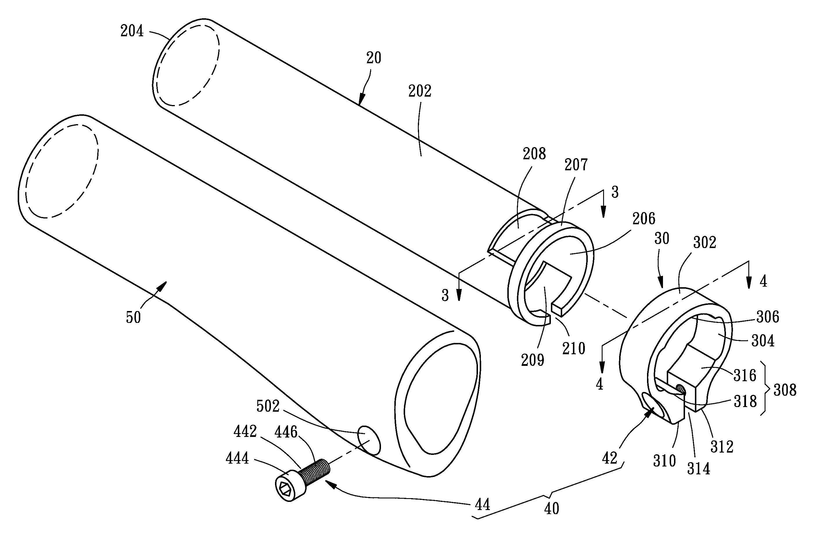
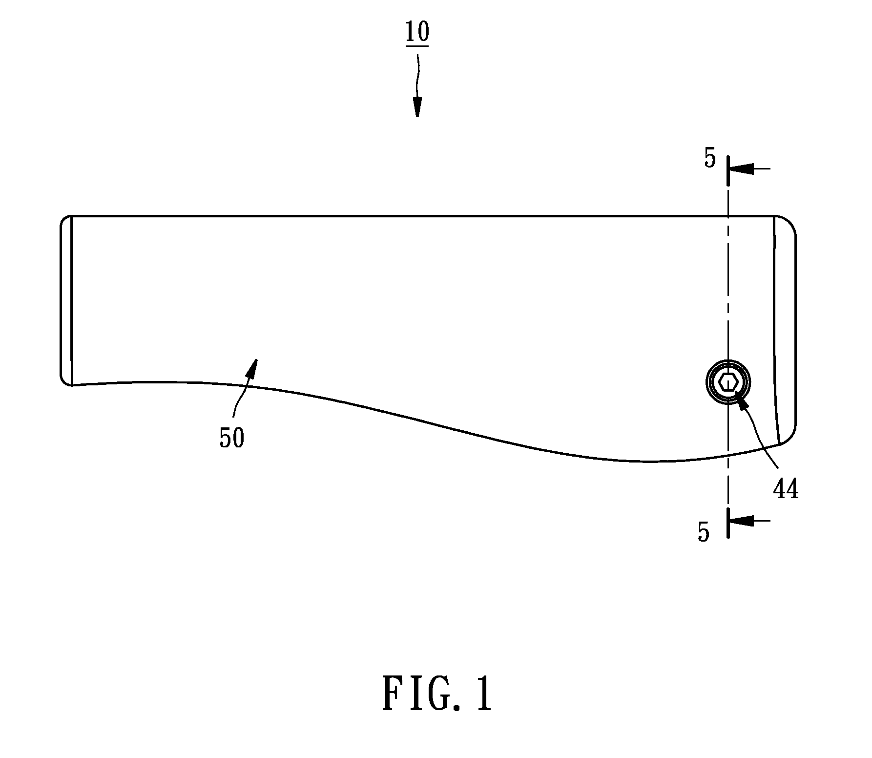
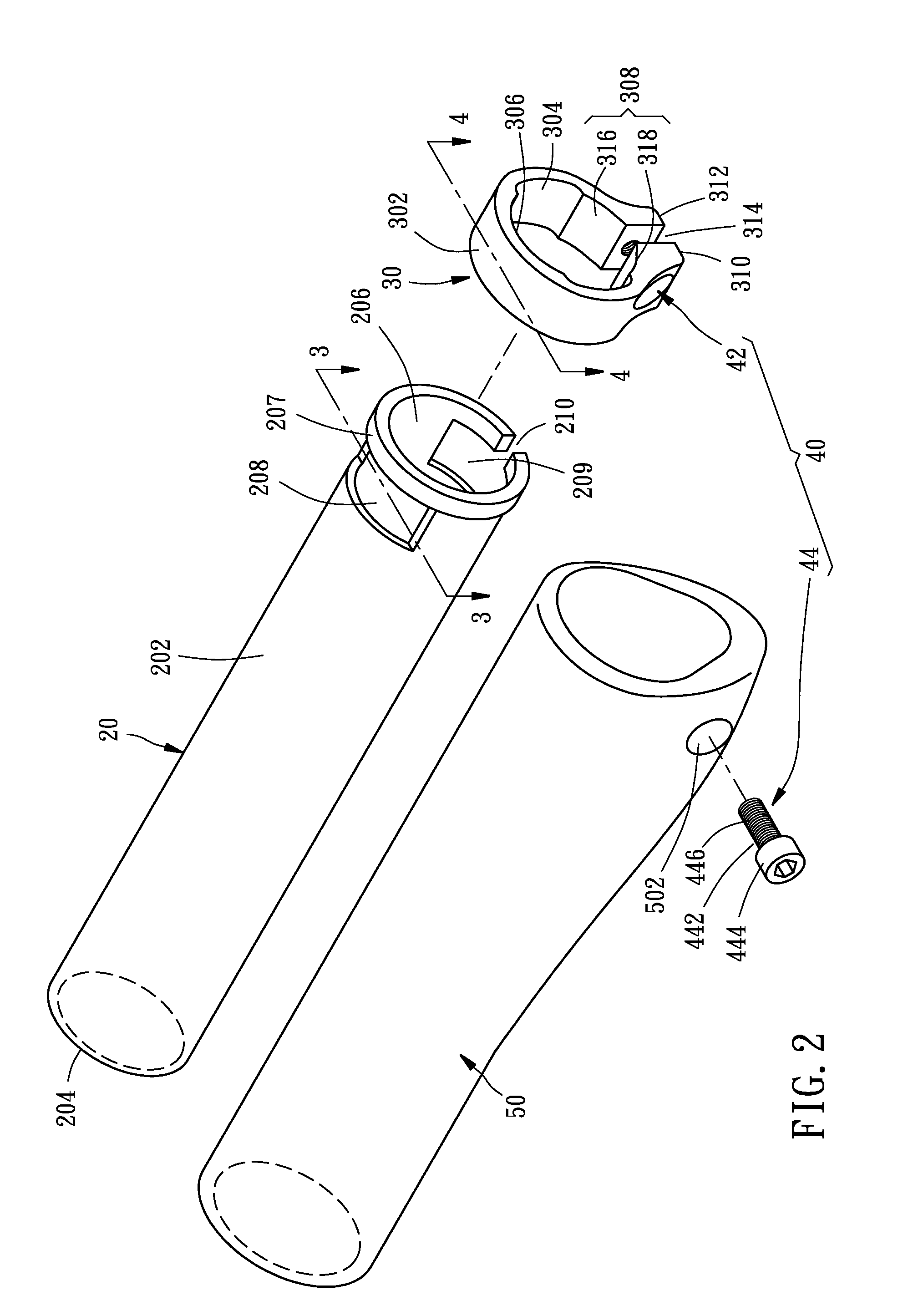
[0018]Please referring to the drawings, handlebar grip 10 is a preferred embodiment according to the present invention. It includes a sleeve 20, a clamping device 30, a fastening means 40 and a covering 50.

[0019]Sleeve 20 in this embodiment is molded from rigid plastic materials and has a cylindrical body 202 with a circularly shaped cross section. Sleeve 20 further has a front opening end 204, a rear opening end 206 with a flange edge 207, a first vacant area 208 and a second vacant area 209 oppositely disposed near rear opening end 206. Each of vacant areas 208, 209 has an arced cross section with a central angle θ between π / 6 to ⅔π. It is believed that the preferred central angle θ is ⅔π (shown in FIG. 3). Flange edge 207 of rear opening end 206 of sleeve 20 has a gap 210 corresponding to second vacant area 209. The width of gap 210 is smaller than that of second vacant area 209.

[0020]Clamping device 30 is made of metal materials and has a ring-shaped body 302 with an annular inn...


PUM


Abstract

A handlebar grip comprises a sleeve, a clamping device and a fastening means. The sleeve made of rigid plastic materials includes a cylindrical body, a front opening end, a rear opening end and at least a vacant area near the rear opening end. The clamping device includes a ring-shaped body, a first extending end and a second extending end. A slot is defined by the first and second extending ends. The clamping device further has at least a protruding disposed on the inner surface of the body. The clamping device is fitted around the rear opening end of the sleeve in such a way that the protruding of the clamping device is wedged into the vacant area of the sleeve. The fastening means includes a threaded bore and a screw. The bore extends through the first and second extending ends of the clamping device along a reference axis. The screw has a shaft with a proximal end and a distal end opposite the proximal end, a head disposed on the proximal end and a threaded region. The screw is adapted for insertion into the bore such that when the screw is advanced, the width of the slot of the clamping device is reduced and in the same time a fastening force is produced radially inwardly toward the rear end of the sleeve so that the sleeve can be firmly mounted on the handlebars.

Description

BACKGROUND OF THE INVENTION[0001]1. Field of the Invention[0002]The present invention relates to grips for the handlebars of a bicycle, and more particularly to a grip which can be firmly mounted to and easily removed from the handlebars of a bicycle.[0003]2. Description of the Related Art[0004]It is known that traditional grips are formed by a substantially cylindrical body which is made of plastic material, is internally hollow and can be inserted onto the ends of handlebars generally formed by suitably shaped metal tubes.[0005]Such prior art grips are designed to have a particular inner diameter being somewhat smaller than the outer diameter of the handlebars so that they can be tightly mounted thereon for avoiding slippage between the grip and the handlebar. Because of this, the mounting as well as the removal of such grips is difficult and time-consuming.[0006]Another problem with such conventional grips is that they can slacken due to factors of aging or environmental impact s...

Claims


Application Information

Patent Timeline
Patent Type & Authority Applications(United States)
IPC IPC(8): B62K21/26
CPCY10T74/20828B62K21/26
Inventor YU, TSAI-YUN
Owner YU TSAI YUN
Why Eureka
Try Eureka