Optical image-capturing apparatus
an image-capturing apparatus and optical technology, applied in the field of optical image-capturing apparatus, can solve the problems of disadvantageous restrictions in optical resolution characteristics, inconvenient configuration for imaging at low light intensity, and significant constraints on the optical design with respect to the arrangement of components, etc., to achieve simple electrical control, high resolution, and high resolution.
- Summary
- Abstract
- Description
- Claims
- Application Information
AI Technical Summary
Benefits of technology
Problems solved by technology
Method used
Image
Examples
embodiment 1
[0080
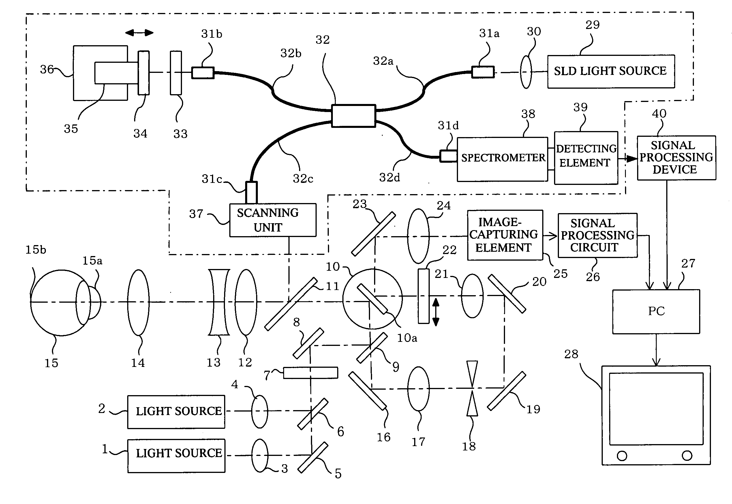
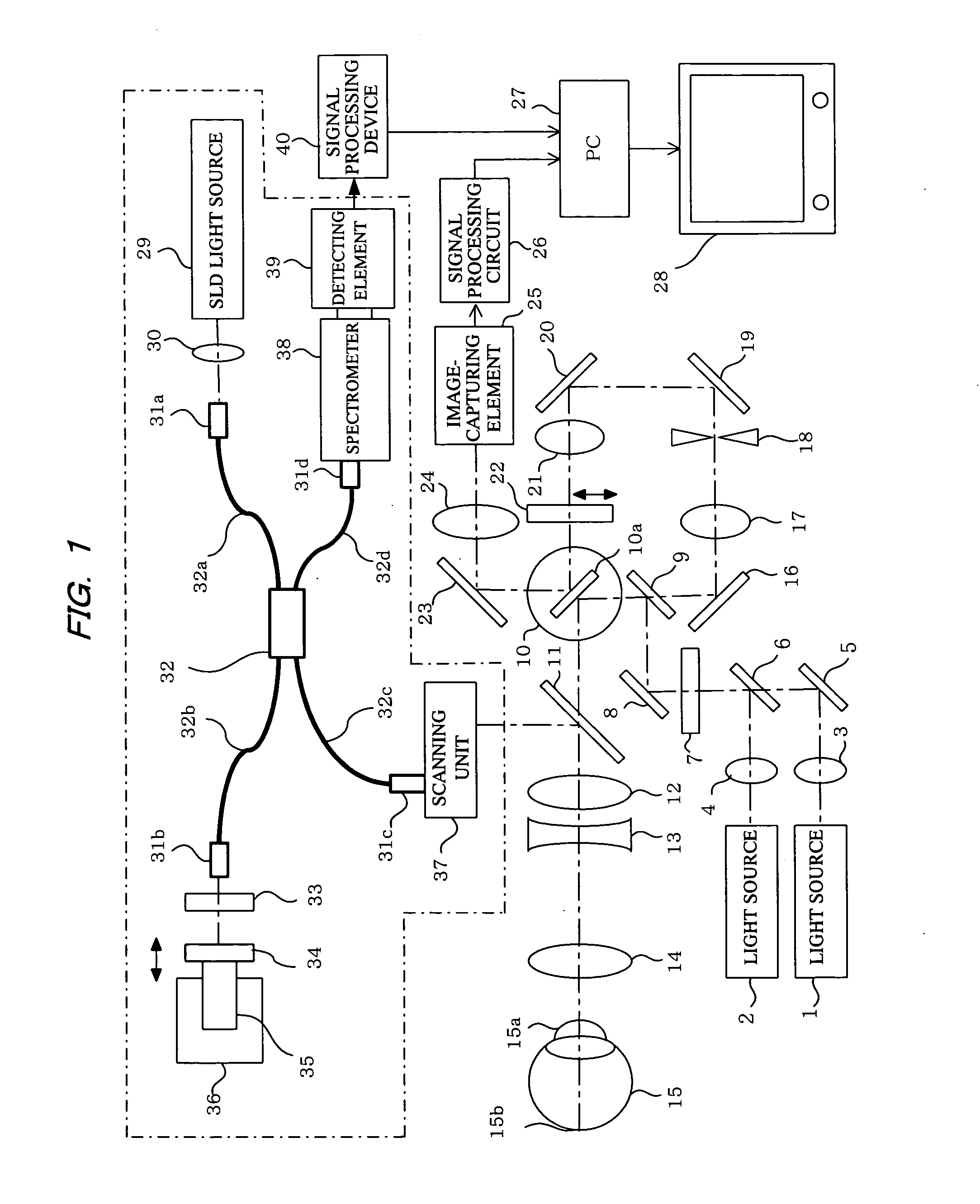
[0081]In FIG. 1, reference numerals 1 and 2 denote light sources (first light source) used to observe a reflection image or a fluorescent image of an object to be observed. These are predetermined light sources with high luminance such as a light-emitting diode that generates high-luminance light beams (a super luminescent diode or SLD), a semiconductor laser (laser diode), or a solid-state laser. The wavelength is, for example, within a range from approximately 490 nm to 800 nm. Light sources 1 and 2 can be used selectively if necessary in order to use different light beams with different wavelengths as required. The light beams from the light sources 1, 2 are collimated by lenses 3, 4, and combined on the same optical axis via a mirror 5 and a dichroic mirror 6.
[0082]The light beam via the mirror 5 and the dichroic mirror 6 is transformed into a flat line beam (a light beam focused linearly on the focal plane) via a cylindrical lens 7, is reflected by a mirror 8, and is made ...
embodiment 2
[0106
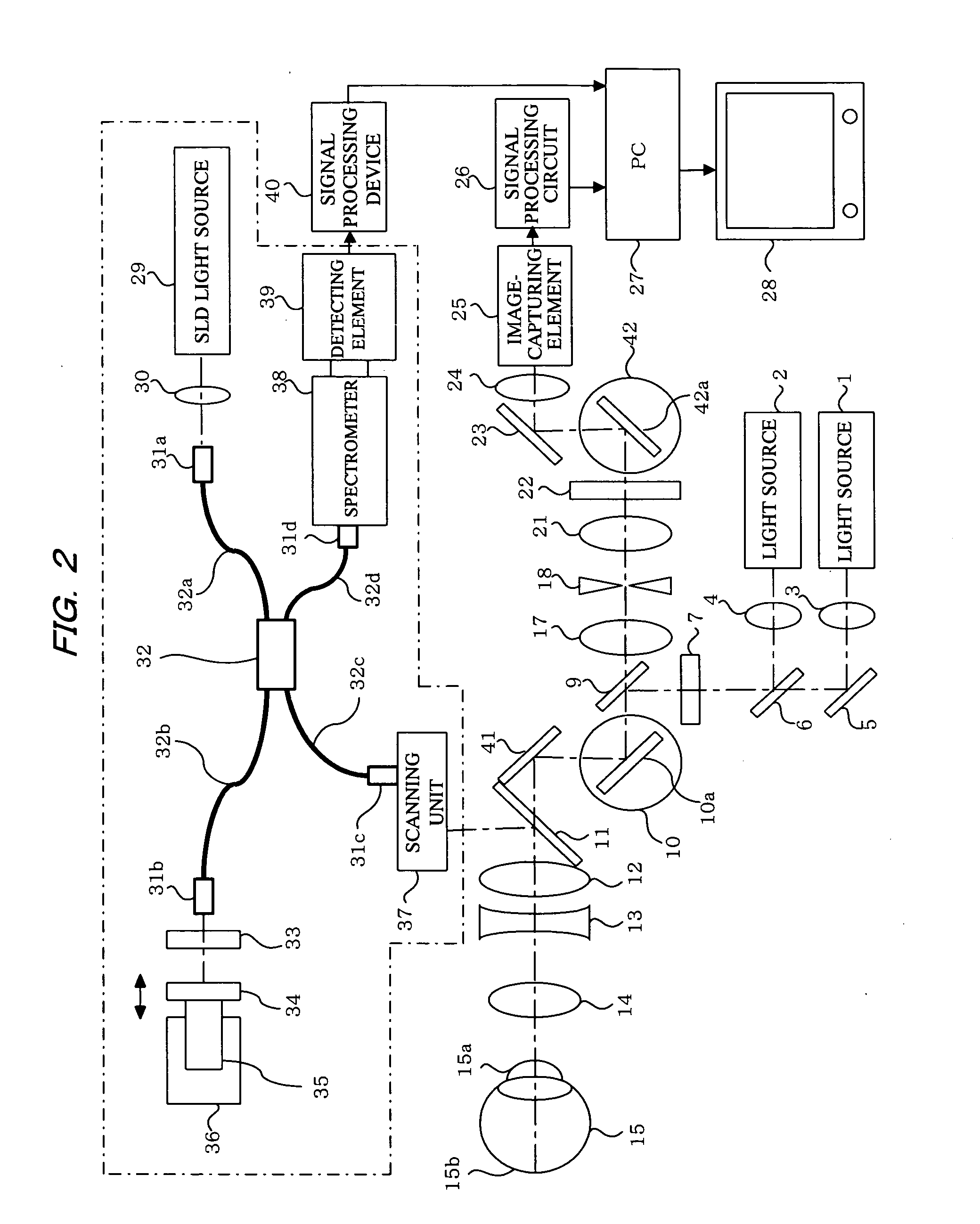
[0107]FIG. 2 shows a system configuration of the embodiment of the present invention that differs from the embodiment in FIG. 1. In FIG. 2, the object to be observed is also assumed to be a human eyeball (anterior ocular segment or ocular fundus). In FIG. 2, the elements identical to the structural elements in FIG. 1 are denoted by the same reference numerals. The structural elements denoted by the same reference numerals in FIG. 2 have the same configuration and function as those in FIG. 1. The following is primarily a description of the points of difference with FIG. 1.
[0108]Light beams from the light sources (SLD or LD) 1, 2 for observing a reflection image or fluorescent image pass through the dichroic mirror 6 and the like, and are shaped by the cylindrical lens 7 into a line beam (slit-shaped beam) which is linear at the focal position. The light beam shaped into a slit is reflected by the beam splitter 9 (BS, optical path splitting member), and then scanned one-dimension...
PUM
 Abstract
Description
Claims
Application Information
 - R&D
- Intellectual Property
- Life Sciences
- Materials
- Tech Scout
- Unparalleled Data Quality
- Higher Quality Content
- 60% Fewer Hallucinations
Browse by: Latest US Patents, China's latest patents, Technical Efficacy Thesaurus, Application Domain, Technology Topic, Popular Technical Reports.
© 2025 PatSnap. All rights reserved.Legal|Privacy policy|Modern Slavery Act Transparency Statement|Sitemap|About US| Contact US: help@patsnap.com


