
Power charging device for an electric vehicle

a charging device and electric vehicle technology, applied in the direction of electric devices, hybrid vehicles, light-to-electric conversion, etc., can solve the problems of insufficient protection of fuse components, insufficient protection measures in the event of indirect contact, etc., to prevent further damage to the electronics of the vehicle or the power charging device. , the effect of increasing the electric safety

Active Publication Date: 2011-11-10
BENDER SA
View PDF0 Cites 67 Cited by
  • Summary
  • Abstract
  • Description
  • Claims
  • Application Information

AI Technical Summary

Benefits of technology

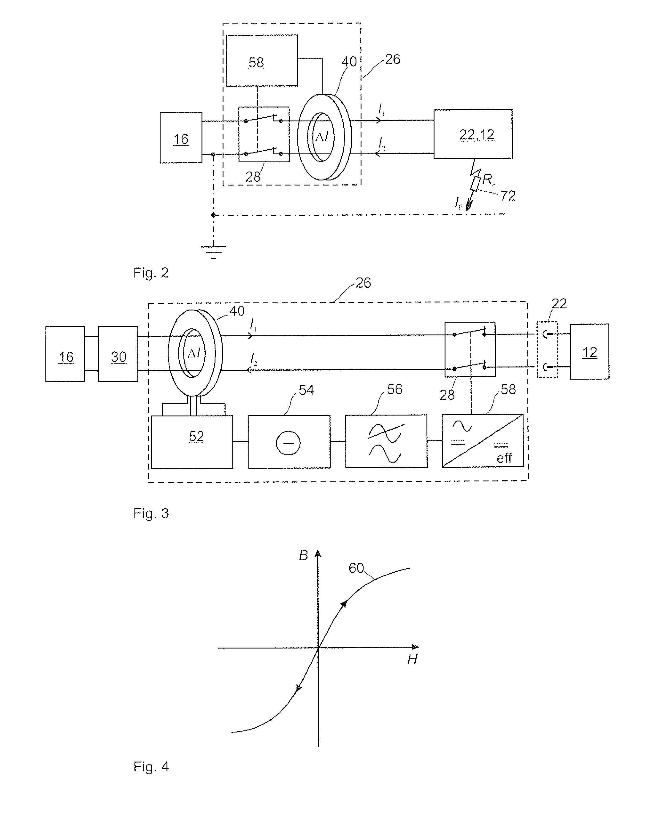
[0006]In order to provide improved protection in the event of indirect contact and against fault currents, the power charging device comprises a residual current monitoring device which is designed to detect a direct current difference ΔI, wherein the charging process is interrupted if a predeterminable direct current cutoff difference is exceeded over a predetermined cutoff period, the residual current monitoring device comparing at least the sum of the incoming current I1 with the return current I2 and determining from this a direct current difference ΔI. If the direct current difference ΔI exceeds a predeterminable direct current cutoff difference ΔImax and if this predeterminable direct current cutoff difference is exceeded over a predeterminable cutoff period ΔT, the charging process is interrupted. If an external d.c. voltage is supplied to a power charging device and a fault current occurs, the charging process can thus be cut off in a reliable manner, in such a way that no fault currents flow and there are no undesired voltage potentials which, in the event of contact by an individual, may pose a dangerous risk. Fault currents, which cannot be detected by a conventional type A (alternating current differential fault) residual current device (RCD) and which pose a risk to humans, can thus be reliably detected. The power charging device is thus able to monitor a safe, i.e. nonhazardous charging process of an electric vehicle and can be subsequently integrated, for example, in a public charging pump which is already provided so as to satisfy or go beyond necessary safety standards. The residual current monitoring device is able to detect both fault currents in the feeding charging system and in the connected electric vehicle as well as in the charging cable between the current evaluation device and the electric vehicle, and can also reliably interrupt the charging process at predetermined cutoff currents and cutoff times for a direct current difference.
[0018]Proceeding from the embodiment above it may further be advantageous if the residual current monitoring device for detecting a current difference comprises a summation current transformer comprising two measurement windings each with an equal number of turns, a push-pull oscillator, an oscillator control unit, a compensation current filtering means and a differential current analysis unit. The measurement windings can be connected as vibration inductances of the push-pull oscillator, and the push-pull oscillator can uniformly traverse a B / H characteristic curve (flux density / field strength characteristic curve / hysteresis characteristic curve) of a yoke of the summation current transformer by means of a compensation current which can be produced by the oscillator control unit, it being possible to split the compensation current through the compensation current filtering means into a direct current difference portion and an alternating current difference portion, and to monitor said compensation current by the differential current analysis unit for an overshoot of a predeterminable direct current and / or alternating current cutoff difference over a predeterminable cutoff time. If the current cutoff difference is exceeded during a predeterminable cutoff time, the differential current analysis unit can activate the cutoff element in order to interrupt the charging process, the cutoff element interrupting the supply of direct current to the vehicle. The residual current monitoring device consequently operates by the principle of a magnetic compensation which is adapted for detection of direct, alternating and mixed currents. The two windings each with an equal number of turns N located on the summation current transformer are connected in the oscillating circuit of the push-pull oscillator as inductors in order to produce oscillation. The characteristic curve of the yoke of the summation current transformer is constantly traversed by the vibration of the push-pull oscillator until it is in the saturation range. Direct current magnetisations are thus compensated. In order to control the push-pull oscillator an oscillator control unit generates a compensation current which can be directly proportionally influenced by the a.c. and d.c. portions of the current difference. This compensation current can be separated electronically in accordance with current type by a compensation current filtering means and evaluated, the differential current analysis unit possibly triggering the cutoff element if a predeterminable value of a current difference, for example depending on current type (direct current difference, pulse current difference, alternating current difference or differences between mixed current types) is exceeded, or if a predeterminable value of an absolute current difference for all current types is exceeded, so that the charging process is interrupted. Based in the principle of known residual current devices (RCDs), a residual current monitoring device can thus be proposed which can provide a reliable charging process, which poses no risk to individuals, for an electric vehicle.

Problems solved by technology

Such protective measures, which are known from the prior art, in the event of indirect contact are hardly sufficient with the extensive use of electric vehicles for ensuring reliable protection of the vehicle occupants and of the technical equipment used.
The conventional protective measures presented above, in particular fuse protection by type A residual current devices (RCDs), which can only recognise alternating current differential faults, are not sufficient to ensure comprehensive protection in the event of indirect contact and against damage or destruction of the vehicle electronics, since they fail when it comes to reliable detection of direct current faults or of alternating current faults (the alternating current being superposed by a direct current), as may occur during operation of an electric vehicle.

Method used


Image

  • Power charging device for an electric vehicle
  • Power charging device for an electric vehicle
  • Power charging device for an electric vehicle

Examples


Embodiment Construction

[0027]In the figures, like or similar components are denoted by like reference numerals.

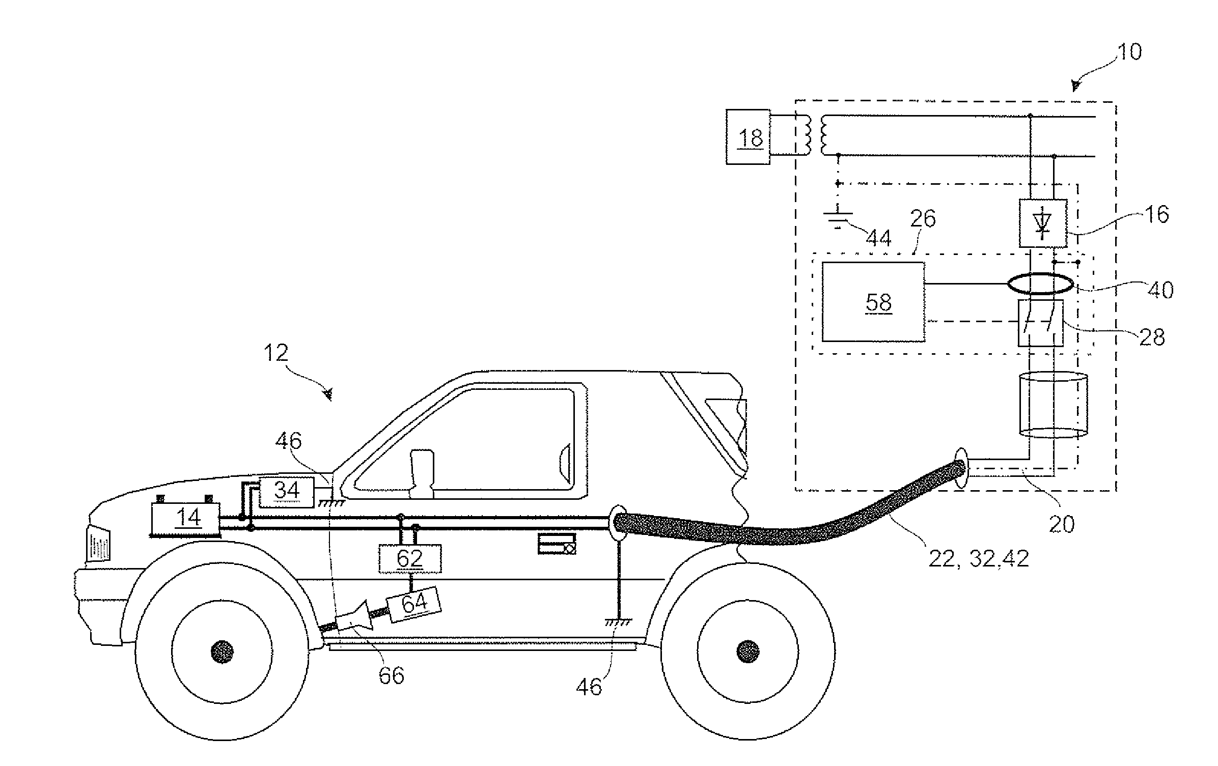
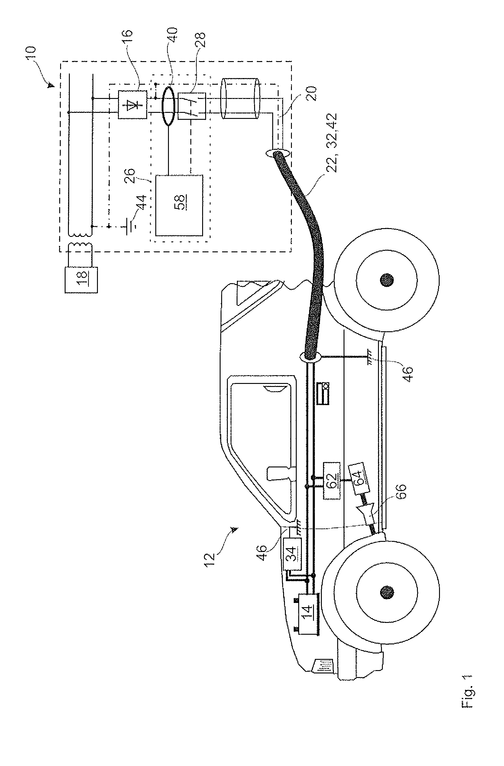
[0028]FIG. 1 is a schematic view of a first embodiment of a power charging device 10, which is connected in this instance to a rechargeable battery of an electric vehicle 12 in order to charge an energy store 14. The power charging device 10 is connected by means of a contacting means 22, which comprises a connection cable and contacts a plug connection terminal on the side of the power charging device 10 and a socket connection terminal on the side of the electric vehicle 12. The contacting means 22 further comprises a data communication channel which, by means of a PWM modulated signal, modulates data over a live conductor for charging the energy store 14. The contacting means 22 further comprises a protective conductor connection 42 which connects the earth 44 of the power charging device to the vehicle earth 46, which is formed by the vehicle chassis, in order to produce an equipotential bond...


PUM


Abstract

The invention relates to a power charging device (10) for an electric vehicle (12) with an electric energy store (14). The power charging device (10) comprises at least one rectifier means (16) for converting a supply voltage (18) into a charging d.c. voltage (20), a contacting means (22) for contacting a plug-in connection supply point (24) of the electric vehicle (12), and a residual current monitoring device (26) for detecting a current difference in the contacting means (22) and / or the electric vehicle (12) during a charging process of the energy store (14) of the electric vehicle (12). The invention is characterised in that the residual current monitoring device (26) is designed at least for detection of a direct current difference ΔI and comprises a cutoff element (28) which can interrupt the charging process when a predeterminable direct current cutoff difference (36) is exceeded over a predeterminable cutoff time.

Description

[0001]The invention is based on a power charging device for an electric vehicle with an electric energy store, comprising at least one rectifier means for converting a supply voltage into a charging d.c. voltage, a contacting means for contacting a plug-in connection supply point of the electric vehicle and a residual current monitoring device for detecting a current difference in the contacting means and / or the electric vehicle during a charging process of the energy store of the electric vehicle.[0002]In order to charge an energy store of an electric vehicle, this term being understood to include both electric vehicles driven purely by electricity and also hybrid vehicles which contain an alternate combination of a drive by electricity and a drive by combustion engine, electrical energy is drawn from an energy mains during downtime. The electric vehicle is normally coupled to the mains supply by means of a connection cable which is plugged into a power point, or which is connected...

Claims


Application Information

Patent Timeline
IPC IPC(8): H02J7/04
CPCB60L3/0023Y02E60/721Y02T10/7005Y02T90/121Y02T90/14B60L3/0069B60L3/04B60L8/003B60L8/006B60L11/1842B60L11/1844B60L11/1846B60L11/185B60L2240/549B60L2250/10Y02T90/169Y02T10/7083Y02T90/128Y04S10/126Y04S30/14B60L11/1816Y02T10/7072B60L53/14B60L55/00B60L53/63B60L53/65B60L53/11Y02E60/00Y02T10/70Y02T90/12Y02T90/167
Inventor HOFHEINZ, WOLFGANG
Owner BENDER SA
Learn More