
Energy Generation System for Electric, Hybrid and Conventional Vehicles

a technology of energy generation system and electric vehicle, which is applied in the direction of energy harvesting concepts, machines/engines, transportation and packaging, etc., can solve the problems of large scale of turbines and requiring ample wind speed, device however is bulky in nature, and does not take into account the streamline shape of vehicles known today, so as to maximize the electrical energy generation of vehicles, reduce the effect of battery loss and large rang

Inactive Publication Date: 2011-11-03
GUZELIMIAN HARRY L
View PDF4 Cites 26 Cited by
  • Summary
  • Abstract
  • Description
  • Claims
  • Application Information

AI Technical Summary

Benefits of technology

[0022]Hybrid and electric vehicle owners take great pride in not only the reduced environmental impact of such vehicles but also the savings in cost associated with fuel economy achieved by the use of electric batteries. However inclement weather such as extreme cold or heat, the range of travel promised by most manufacturers is nearly cut in half. Therefor it is the advantage of the present invention to provide heat exchanger means at or near the battery compartment.
[0023]For example in extreme cold weather, captured and heated airstreams as previously disclosed may be directed to an insulated battery compartment housing as a heat exchanger means to heat the battery to a normal operating temperature. Alternatively in extreme heat, the captured airstream driving fans of an alternator may be used to power a compressor or the like to further cool the captured air and direct it to a heat exchanger means at or near the battery compartment to effectively cool a battery as needed.
[0024]Alternatively, because the vehicle generates electrical energy while parked outside where wind powers the fans or turbines and attached electrical generation means, the system herein may be employed to heat batteries by using resistive electrical heating means such as an electric blanket. In this mode, the electrical energy generated while parking is operatively communicated to a resistive heat generation device adjacent to, or surrounding a battery. Heat so generated will maintain the battery withing operative temperature ranges which is especially important on hybrid and fully electric vehicles lest they lose a great deal of range due to chilled batteries.
[0025]In the passive mode of electrical energy generation, the system will generate electrical energy from ambient wind directed against the vehicle. The funneled intake apertures are formed such that they intake a sufficient amount of moving air to generate energy when the car is moving. But, some or all of the intake apertures can concurrently be placed at such an angle as to allow for natural wind from a plurality of approaching angles, to turn the fan blades and continue to charge vehicle batteries. For vehicles sitting in long term parking or otherwise parked for long periods, this energy generating will keep the batteries charged. Further if desired, should the vehicle be parked in the sun, the exiting airstreams may be channeled through the passenger compartment to keep it reasonably cool.
[0026]As such, the disclosed device and method maximizes the electrical energy generation of the vehicle while moving and while parked. Concurrently while moving, the airstream may be employed to heat the passenger compartment or defrost the windshield, and, while stationary, the airstream may cool a sunbaked car.
[0027]It is an object of this invention to provide an electrical energy generation system adapted to generate electrical power while the vehicle is moving.

Problems solved by technology

These turbines are large in scale and require ample wind speeds to produce usable energy.
The device however is bulky in nature and does not take into account the streamline shapes of vehicles known today.
Further, Stoeckert makes no accommodation for capturing wind energy from all directions of a stationary vehicle to ensure constant electrical generation while the vehicle is parked.

Method used


Image

  • Energy Generation System for Electric, Hybrid and Conventional Vehicles
  • Energy Generation System for Electric, Hybrid and Conventional Vehicles
  • Energy Generation System for Electric, Hybrid and Conventional Vehicles

Examples


Embodiment Construction

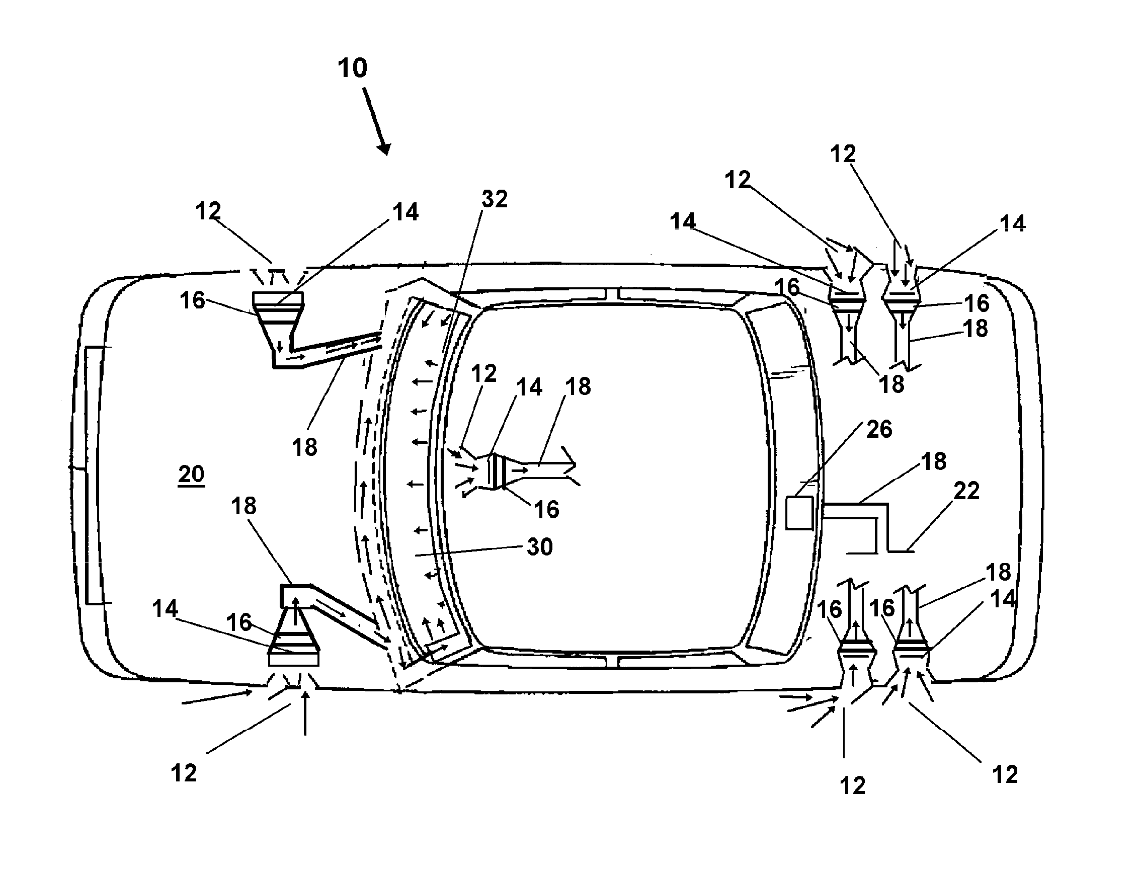
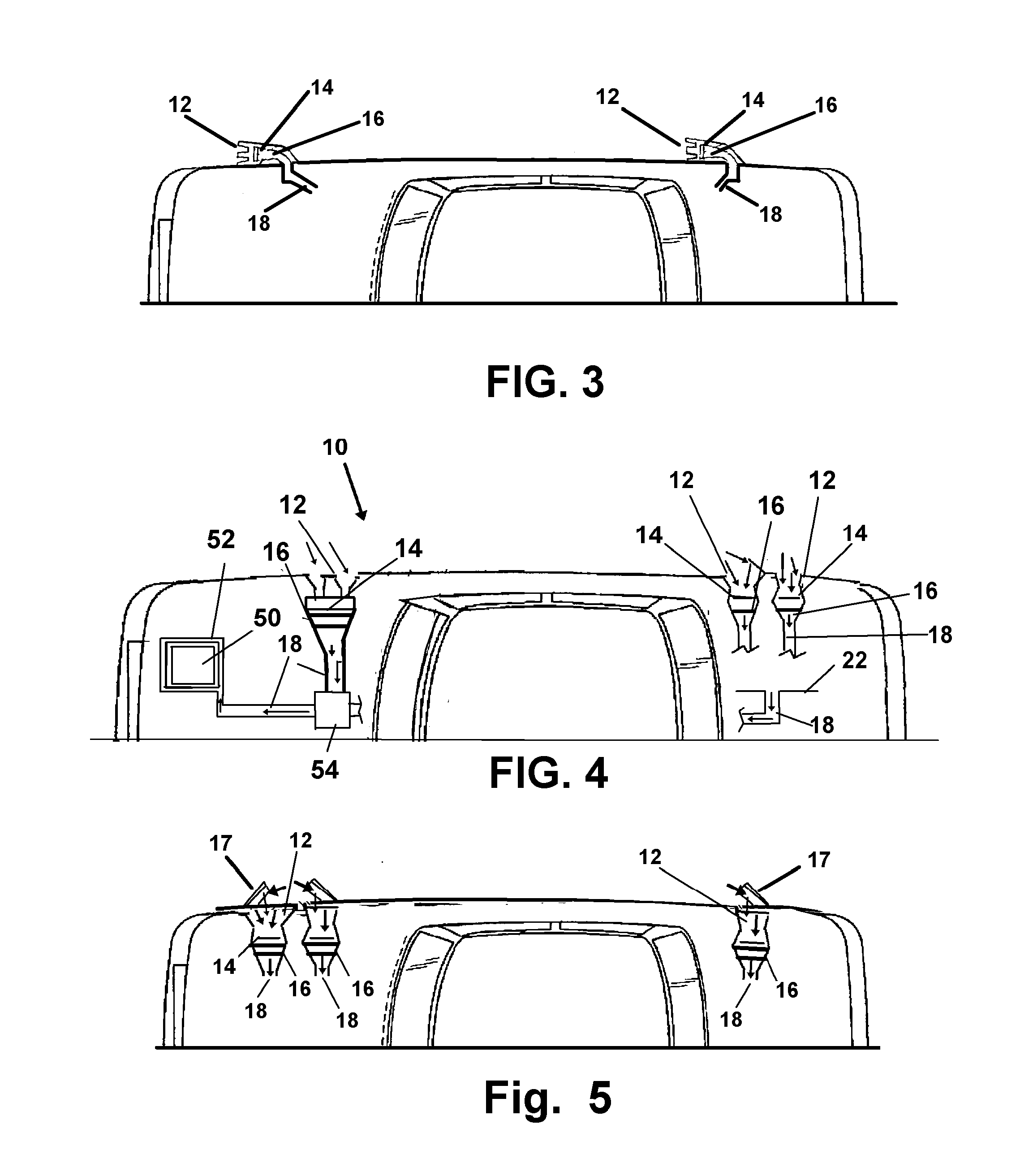
[0038]Referring now to the FIGS. 1-5, wherein similar components are depicted using like numerals for identification, in FIG. 1 there is shown a plurality of recessed or aerodynamic intake apertures 12 which may be used alone, or in combination with other modes which project or have deflectors 17 which are further described herein.

[0039]As noted, the air intakes 12 are positioned to take advantage of both airstreams available. First, the airstreams developed for and from the moving car which generally run inline with the vehicle's direction of travel. Second, the airstreams from wind approaching a parked vehicle at different angles.

[0040]By situating intake apertures 12 facing the front and sides of the vehicle, two potential airstreams may be captured to generate electrical energy. The system 10 herein employing these apertures 12 at differing angles, communicates a plurality of airstreams to provide a rotational force to a plurality of rotatable fans 14 which are in operative posi...


PUM


Abstract

The vehicle electrical energy generation system which employs one or a plurality of fans operatively engaged with a generator or alternator to generate electrical power. Incoming wind moves past fans engaged to rotate alternators or generators and exits to a secondary conduit as moving air. The moving air is directed to one or a plurality of conduits leading to one or a plurality of moving-air employing components from a group including, a de-fogging component, a windshield defroster, a windshield de-icing component, a wind powered windshield wiper, a passenger heating system, a battery heating component, and a battery cooling compartment.

Description

[0001]This application claims priority to U.S. Provisional Application 61 / 328,959 filed on Apr. 28, 2010 and incorporated herein in its entirety by this reference.BACKGROUND OF THE INVENTION[0002]1. Field of the Invention[0003]The current invention relates generally to alternative means to electrically power in real time, or charge a power storage means, for a motor vehicle. More particularly it relates to a system to harness wind energy from either of a moving vehicle, or ambient wind originating substantially any direction surrounding a stationary vehicle, to create electrical energy for storage and vehicle use. Additionally, air traversing the turbine powered generators may be employed for heating components of the vehicle, clearing a windshield, or in cold climates, for heating of a battery or surrounding compartment.[0004]2. Prior Art[0005]Machines used to capture wind energy have been seen as far back as 200 B.C. Modern wind turbines are used more and more commonly for large s...

Claims


Application Information

Patent Timeline
Patent Type & Authority Applications(United States)
IPC IPC(8): B60K16/00
CPCB60K16/00B60K2016/006Y02T10/7083Y02T10/90B60L8/006Y02E10/728Y02T10/7072Y02E10/72F03D9/32F03D9/25
Inventor GUZELIMIAN, HARRY L.
Owner GUZELIMIAN HARRY L
Learn More