
Electric power steering apparatus

Active Publication Date: 2011-10-27
MITSUBISHI ELECTRIC CORP
View PDF6 Cites 8 Cited by
  • Summary
  • Abstract
  • Description
  • Claims
  • Application Information

AI Technical Summary

Benefits of technology

[0021]The present invention has been made to solve the above problems, and provides an electric power steering apparatus which is capable of releasing or lessening the limit on the number of repetitions or continuous time of the “stationary steering” or the “end contact”.
[0023]With such a configuration, in a case where the rotational speed is higher than a predetermined value, since it is not necessary to continue or repeat a large amount of auxiliary torque, even though the electric current amplitude is allowed up to the maximum electric current amplitude which can be supplied by a semiconductor power converter at a predetermined rotational speed or above, the number of repetitions or continuous time of the “stationary steering” or the “end contact” is not reduced, and the allowed electric current amplitude becomes smaller than the maximum electric current amplitude which can be supplied by the semiconductor power converter at the predetermined rotational speed or below (low speed region). Thus, it is possible to release or lessen the limit on the number of repetitions or continuous time of the “stationary steering” or the “end contact”.

Problems solved by technology

However, in an rotating AC machine for driving a fan pump, since load may be proportional to a rotational speed or the square of the rotational speed, as the rotational speed is increased, the load becomes large.
On the other hand, in the rotating AC machine provided in the electric power steering apparatus, as the rotational speed is decreased, the load becomes large, unlike the rotating AC machine for driving the fan pump or the like.
Specifically, in steering of the steering apparatus, a large amount of auxiliary torque is required when the steering is performed in a state where the vehicle is stopped, which is called “stationary steering”.
Since the steering speed of the “stationary steering” is not high, the rotational speed of the rotating AC machine which generates the auxiliary torque is also not high.
Further, in a case where a large amount of auxiliary torque is generated in the rotating AC machine, the semiconductor power converter provided in the electric power steering apparatus supplies a large amplitude electric current to the rotating AC machine.
As the electric current amplitude which can be supplied by the semiconductor power converter becomes large, the cost or size of the semiconductor power converter is increased.
However, if the “end contact” continuously occurs, the amount of heat generation is increased as will be described later, and thus, there is a risk of affecting the reliability.
Accordingly, in a case where the rotating AC machine generates a large amount of auxiliary torque by the “stationary steering” or the “end contact”, the loss due to the electric power supply becomes remarkably large.
Thus, if the “stationary steering” or the “end contact” generated in a range where the rotational speed is low is performed, the electric current which can be supplied by the semiconductor power converter becomes the maximum electric current and heat generation also becomes large, to thereby place a limit on the number of repetitions of the “stationary steering” or the continuous time of the “end contact”, which results in the problem that the steering feeling is deteriorated.
Further, in the electric power steering apparatus in the related art which is disclosed in the above-mentioned JP-A-01-186468, since the electric current does not continuously flow for a predetermined time or more so as to restrict heat generation in an allowable range, the number of repetitions of the “stationary steering” or the continuous time of the “end contact” is limited, thereby resulting in the problem that the steering feeling is deteriorated in a similar way.
However, since the steering angle of the “stationary steering” becomes arbitrary, there is a problem that the heat generation due to the “stationary steering” cannot be restricted.
Thus, in order to determine an absolute value of the steering angle, a steering angle detector or the like is required, which causes a problem that the cost of the electric power steering apparatus is increased.

Method used


Image

  • Electric power steering apparatus
  • Electric power steering apparatus
  • Electric power steering apparatus

Examples


first embodiment

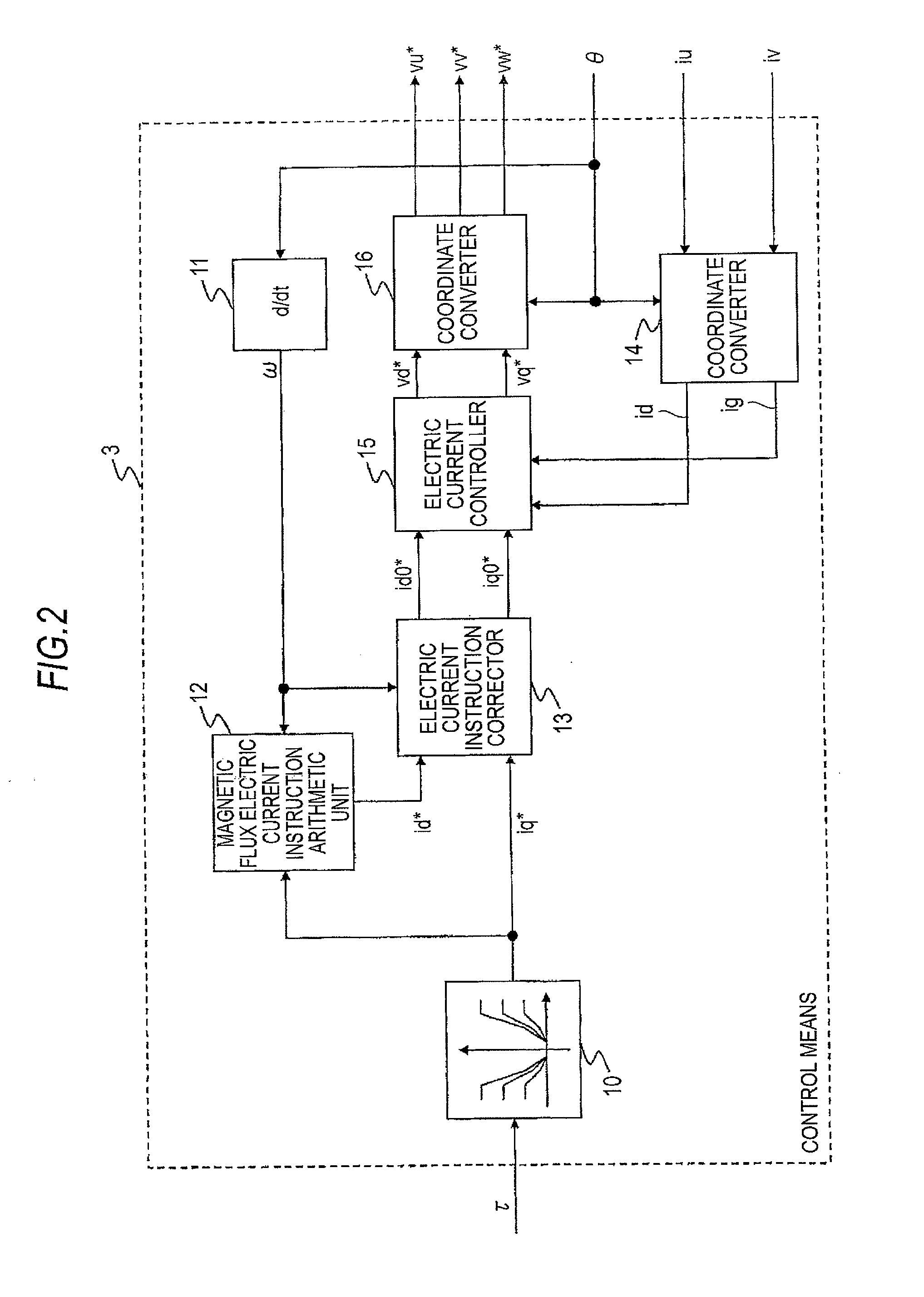
[0035]FIG. 1 is a diagram illustrating a configuration of an electric power steering apparatus according to a first embodiment of the invention. If an operator generates a steering torque of a steering system by a steering wheel 1, a torque detection means 2 detects the steering torque and outputs the detected steering torque as a detection torque τ. In order to generate a torque which assists the steering torque in an rotating AC machine 4, a control means 3 calculates three-phase voltage references vu*, vv* and vw* to be applied to the rotating AC machine 4 on the basis of the detection torque τ obtained from the torque detection means 2, to thereby output the calculation result to a semiconductor power converter 5. In this embodiment, a case where a surface permanent magnet synchronous machine called a DC brushless motor is used as the rotating AC machine 4 is described. However, another rotating AC machine such as an interior permanent magnet synchronous machine called an IPM mo...

second embodiment

[0064]In the first embodiment, the electric current instruction corrector 13 has the configuration shown in FIG. 3, but may be replaced with an electric current instruction corrector 13a in which the magnetic flux component electric current instruction and the torque component electric current instruction are exchanged with each other. FIG. 5 is a diagram illustrating an internal configuration of the electric current instruction corrector 13a in a second embodiment. Here, like reference numerals are given to the same or equivalent elements as in the first embodiment.

[0065]A corrected torque component electric current instruction arithmetic unit 30 sets a corrected torque component electric current instruction iq0* to −imax in a case where a torque component electric current instruction iq* is smaller than −imax; sets the corrected torque component electric current instruction iq0* to imax in a case where the torque component electric current instruction iq* is larger than imax; and ...

third embodiment

[0068]The electric current instruction corrector 13a according to the second embodiment may be replaced with an electric current instruction corrector 13b shown in FIG. 6. FIG. 6 is a diagram illustrating an internal configuration of the electric current instruction corrector 13b according to a third embodiment. Here, like reference numerals are given to the same or equivalent elements as in the first and second embodiments.

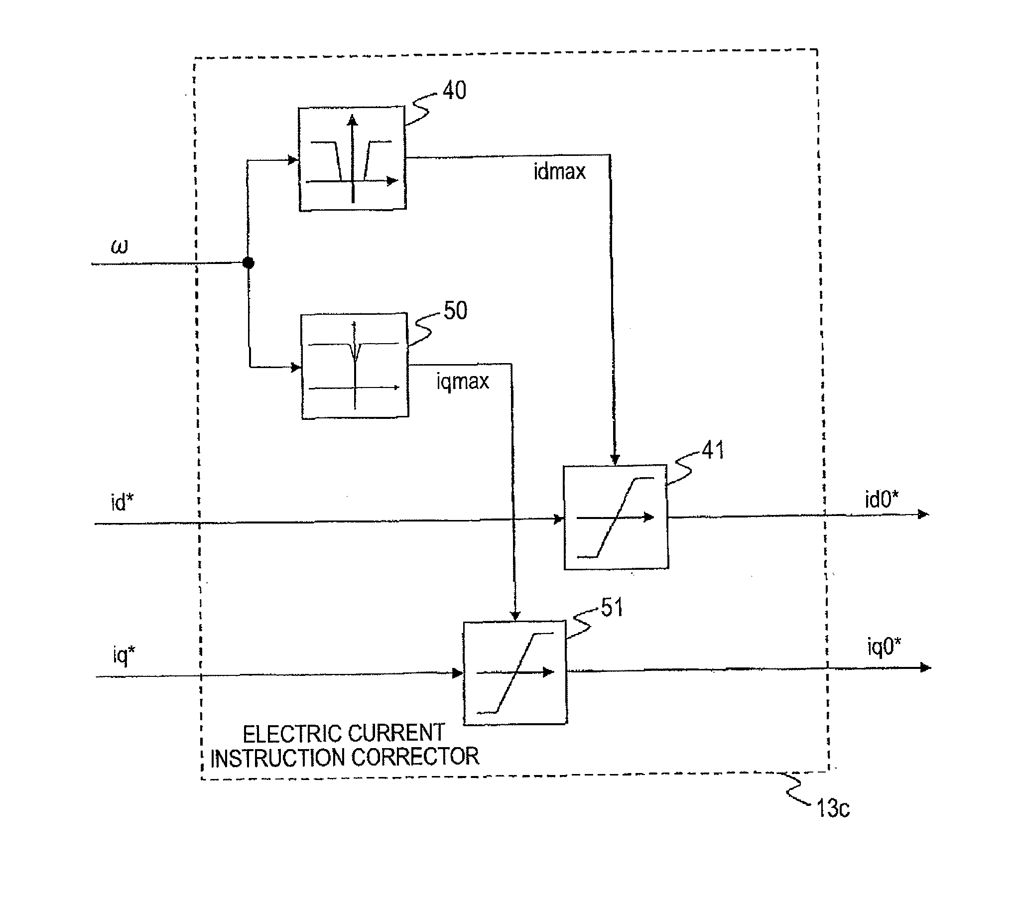
[0069]An allowable magnetic flux component electric current arithmetic unit 40 outputs an allowable magnetic flux component electric current amplitude idmax on the basis of a rotational speed ω. The allowable magnetic flux component electric current arithmetic unit 40 is configured so that if the rotational speed ω is increased, the allowable magnetic flux component electric current amplitude idmax becomes large, and if the rotational speed ω is lower than a predetermined value, the allowable magnetic flux component electric current amplitude idmax becomes zero.

[...


PUM


Abstract

An electric power steering apparatus includes an rotating AC machine which generates an auxiliary torque for assisting a steering torque of a steering system; and a controller which performs control so that the allowed electric current amplitude of the rotating AC machine becomes large if a rotational speed of the rotating AC machine is increased. Accordingly, it is possible to release or lessen the limit on the number of repetitions or continuous time of the “stationary steering” or the “end contact”.

Description

1. FIELD OF THE INVENTION[0001]The present invention relates to an electric power steering apparatus which generates an auxiliary torque for a steering torque of a steering system using an rotating AC machine.2. DESCRIPTION OF THE RELATED ART[0002]There is known an electric power steering apparatus which performs power supply from a semiconductor power converter so as to detect a steering torque of a steering system and to generate an auxiliary torque by an rotating AC machine on the basis of the detected torque.[0003]In general, in a case where the rotating AC machine is driven by the semiconductor power converter provided in the electric power steering apparatus, an alternating current is decomposed into a magnetic flux component electric current and a torque component electric current by means of a technique which is called coordinate transformation, and the torque component electric current is controlled to become a desired value. Thus, it is possible to set torque of the rotati...

Claims


Application Information

Patent Timeline
IPC IPC(8): B62D6/00B62D5/04B62D119/00H02P21/00H02P21/06H02P27/04
CPCB62D5/046B62D5/0469H02P21/06H02P21/0089H02P21/0035H02P21/22
Inventor KIMPARA, YOSHIHIKOKIFUKU, TAKAYUKINAKANO, MASATSUGU
Owner MITSUBISHI ELECTRIC CORP
Learn More