
Image capturing apparatus, method of detecting tracking object, and computer program product

a technology of image capture and tracking object, which is applied in the field of image capture apparatus, a tracking object detection method, and a computer program product, can solve the problems of difficult to set the object as a tracking target, and the inability to start the tracking operation with a moving object as the tracking target,

Inactive Publication Date: 2011-10-27
RICOH KK
View PDF2 Cites 39 Cited by
  • Summary
  • Abstract
  • Description
  • Claims
  • Application Information

AI Technical Summary

Benefits of technology

[0009]It is an object of the present invention to at lea...

Problems solved by technology

However, in the conventional methods, the fact that the tracking target object is selected by the operation of the user, the face detection process, the AF operation, and the like makes it difficult to set the object as a tracking target unless the tracking target object is held still when selecting the object.
In other words, it is difficult to select as a tracking target an object that is moving when starting up the image capturing apparatus, making it impossible to start the tracking operation with a moving object as the tracking target.

Method used


Image

  • Image capturing apparatus, method of detecting tracking object, and computer program product
  • Image capturing apparatus, method of detecting tracking object, and computer program product
  • Image capturing apparatus, method of detecting tracking object, and computer program product

Examples


Embodiment Construction

ulate a motion vector of each of grouped image areas;

[0020]FIG. 7 is a diagram illustrating a way to calculate a moving amount of an object contained in each of the grouped image areas;

[0021]FIG. 8 is a diagram illustrating a way to set a search of a tracking target object; and

[0022]FIGS. 9A and 9B are diagrams illustrating a way to reduce blurring of an object by setting a shutter speed fast when the moving speed of the object is fast.

DETAILED DESCRIPTION OF THE PREFERRED EMBODIMENTS

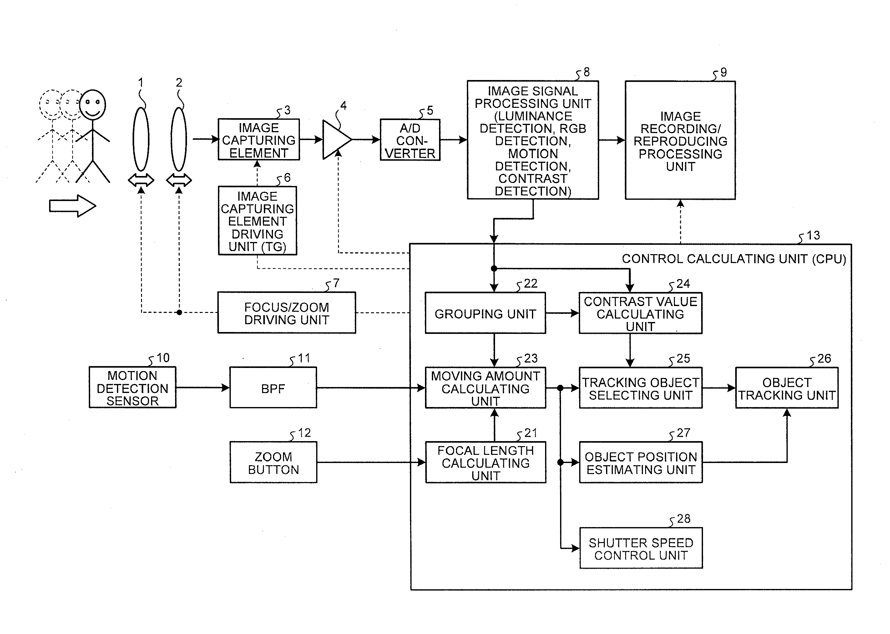
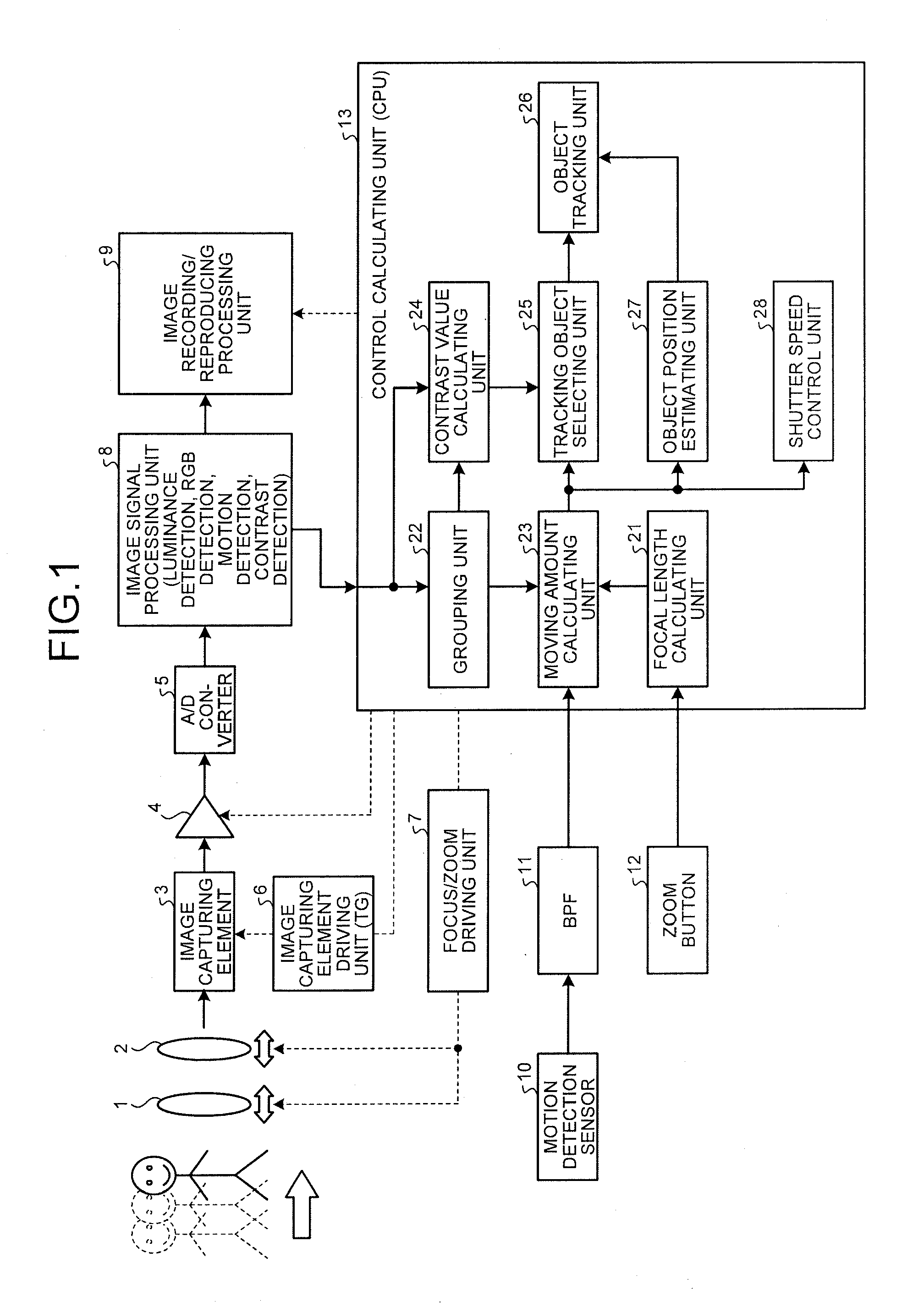
[0023]Exemplary embodiments of an image capturing apparatus and a method of detecting a tracking object according to the present invention will be explained in detail with reference to accompanying drawings below. While a digital camera to which the present invention is applied is exemplified in the following explanation, the invention can be widely applied to any types of image capturing apparatuses having an object tracking function.

[0024]FIG. 1 is a block diagram illustrating an overall structure of ...


PUM


Abstract

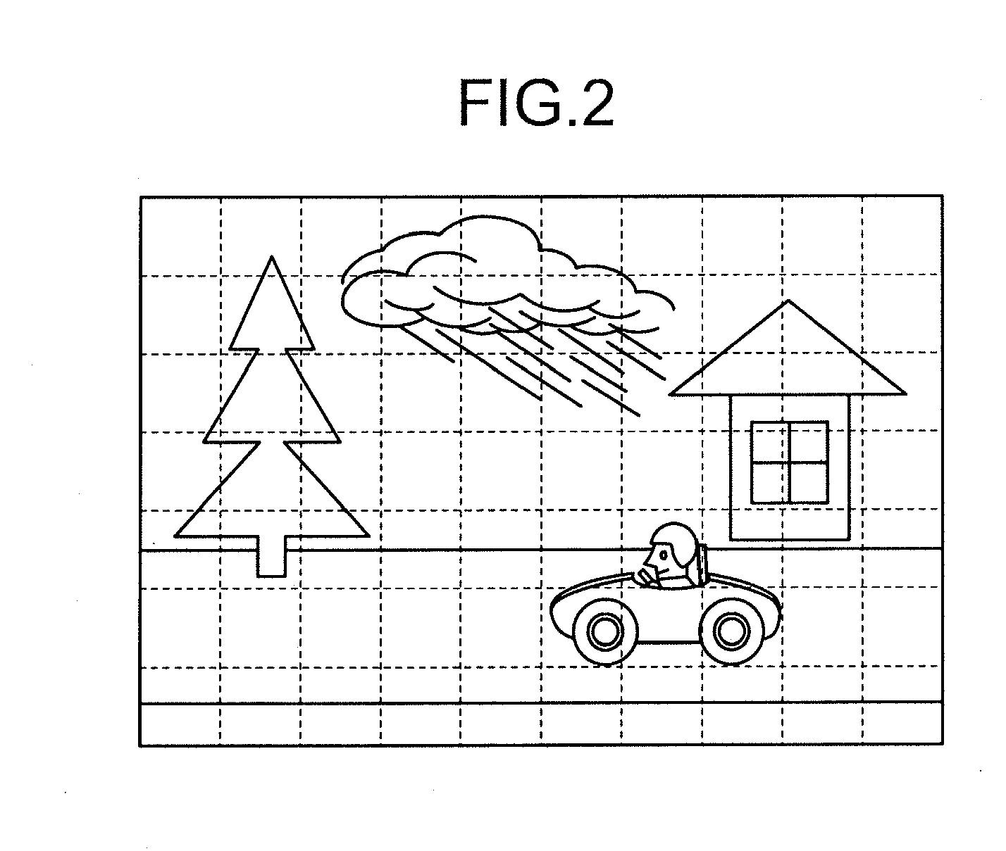
An image signal processing unit partitions a frame image into a plurality of partitioned blocks and calculates for each partitioned block luminance information, color information, contrast information, and a motion vector quantity. A grouping unit groups the partitioned blocks into an image area of the same object based on the luminance information and the color information of each partitioned block. A moving amount calculating unit calculates a moving amount of an object contained in a grouped image area based on the motion vector quantity of each partitioned block, a detection value of a motion detection sensor, and a focal length calculated by a focal length calculating unit. A tracking object selecting unit selects an object in the image area of the highest contrast value as a tracking target object out of objects each having a moving amount exceeding a threshold value.

Description

CROSS-REFERENCE TO RELATED APPLICATIONS[0001]The present application claims priority to and incorporates by reference the entire contents of Japanese Patent Application No. 2010-099936 filed in Japan on Apr. 23, 2010.BACKGROUND OF THE INVENTION[0002]1. Field of the Invention[0003]The present invention relates to an image capturing apparatus, a method of detecting tracking object, and a computer program product.[0004]2. Description of the Related Art[0005]In image capturing apparatuses typified by video cameras and digital cameras, an image capturing apparatus having an object tracking function has been widespread. The object tracking function is a function to move a focus area and such in an image capturing range of the image capturing apparatus in response to the movement of a tacking target of a photographic subject to allow focus adjustment, calculation of an exposure condition, and the like to be carried out by following the moving photographic subject.[0006]In image capturing a...

Claims


Application Information

Patent Timeline
IPC IPC(8): G06K9/00H04N9/73
CPCG06T7/204H04N5/23212G06T2207/10024G06T7/248H04N23/673H04N23/61
Inventor NIINAMI, NORIKATSU
Owner RICOH KK
Learn More