
transformer

a transformer and transformer technology, applied in the field of transformers, can solve the problems of high copper loss, large form-factor, high magnetic loss,

Active Publication Date: 2011-10-27
ENPHASE ENERGY
View PDF6 Cites 11 Cited by
  • Summary
  • Abstract
  • Description
  • Claims
  • Application Information

AI Technical Summary

Problems solved by technology

In order to provide sufficient space for the windings, the winding area of a transformer is generally large as compared to a cross-sectional area of the transformer's core, resulting in a large form-factor as well as high magnetic losses.
Additionally, the large number of windings results in high copper losses.
However, at high frequencies (e.g., hundreds of kilohertz) a design which uses the entire core window will have very large proximity effect losses.

Method used


Image

  • transformer
  • transformer
  • transformer

Examples


Embodiment Construction

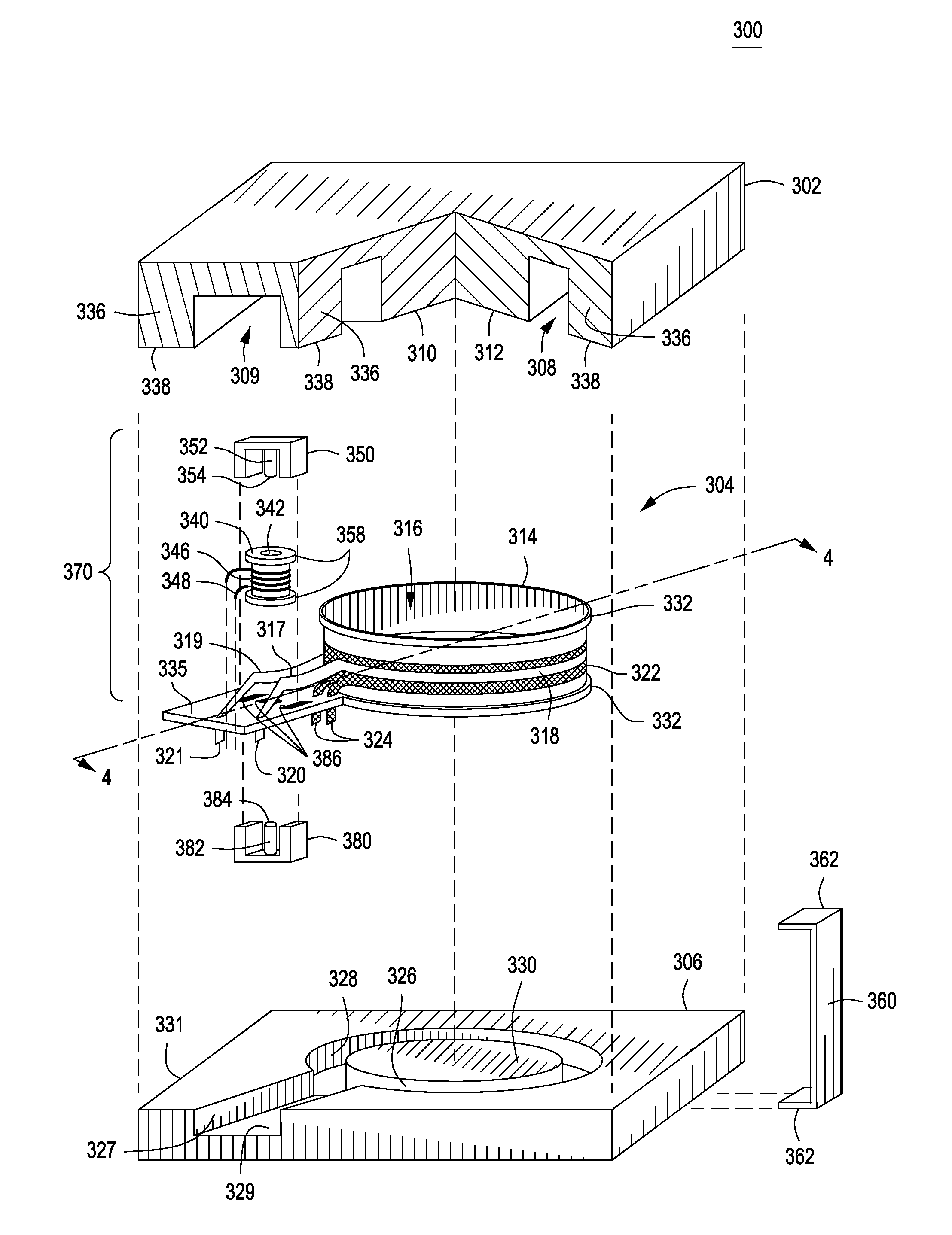
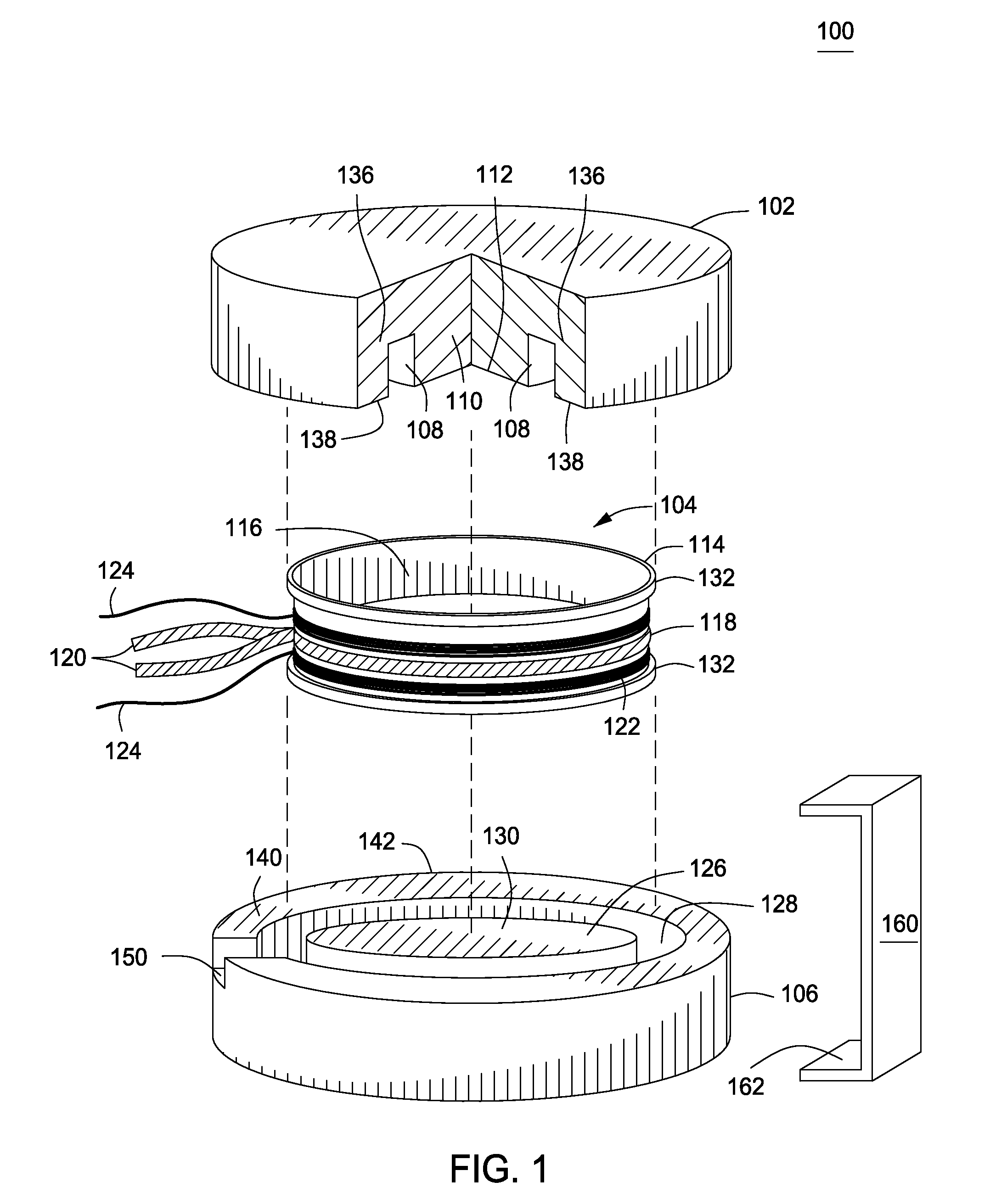
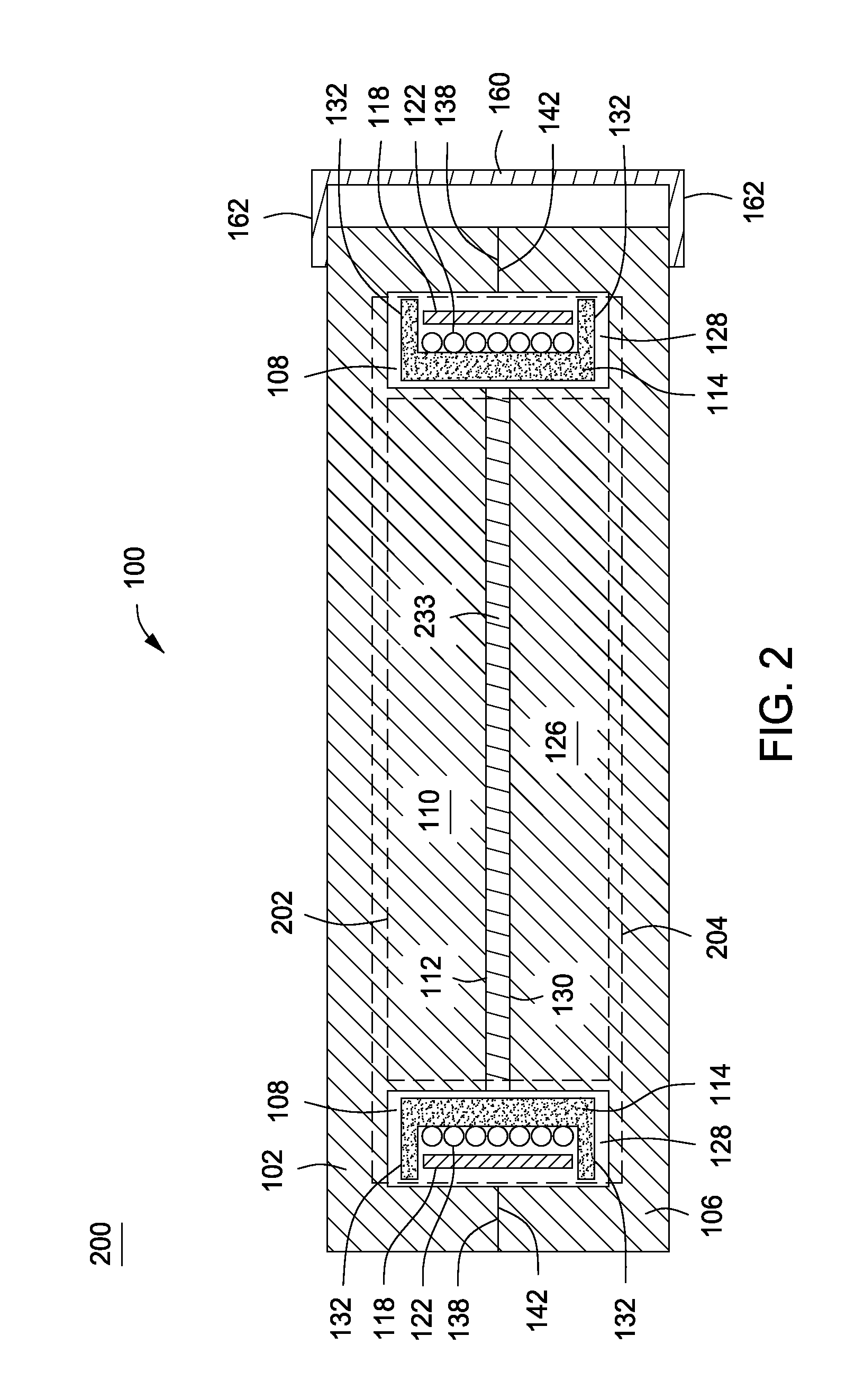
[0019]FIG. 1 is an exploded, perspective view of a transformer assembly 100 in accordance with one or more embodiments of the present invention. The transformer assembly 100 comprises a first pole piece 102, a bobbin winding assembly 104, and a second pole piece 106.

[0020]The first pole piece 102 is depicted as having been partially cut away in order to illustrate the configuration of the first pole piece 102. The first pole piece 102 is comprised of a magnetic material, such as ferrite, and defines an annular channel 108 sized so as to receive the bobbin winding assembly 104; i.e., the first pole piece 102 is a magnetic puck having an annular channel 108 formed in it. The channel 108 defines a post 110 (a first pole). The channel 108 is defined by an outer surface of the post 110 and an inner surface of an annular rim 136. The post 110 and the rim 136 terminate on the underside of the first pole piece 102 in a generally flat post mating surface 112 and a generally flat rim mating s...


PUM

PropertyMeasurementUnit
Electrical inductanceaaaaaaaaaa
Areaaaaaaaaaaa
Areaaaaaaaaaaa

Abstract

A transformer assembly. In some embodiments, the transformer assembly comprises a transformer, comprising a magnetic core; a primary winding wound around the magnetic core, wherein the primary winding comprises one or two turns of a first conductive material; and a secondary winding wound around the magnetic core, wherein the secondary winding comprises a plurality of turns of a second conductive material, and wherein a diameter of the magnetic core is sized such that the transformer achieves a first inductance with a core loss comparable to a winding loss.

Description

CROSS-REFERENCE TO RELATED APPLICATIONS[0001]This application claims benefit of U.S. provisional patent application Ser. No. 61 / 342,371, filed Apr. 13, 2010, which is herein incorporated in its entirety by reference.BACKGROUND OF THE INVENTION[0002]1. Field of the Invention[0003]Embodiments of the present disclosure relate generally to transformers and, more particularly, to a low profile, high frequency, high efficiency transformer.[0004]2. Description of the Related Art[0005]Transformers are used in a variety of devices to perform functions such as altering a voltage level (e.g., converting a mains voltage to low voltage for powering electronics), circuit isolation, measuring voltage or current in electrical power systems, and a host of other functions. Often, transformers will sandwich a primary winding between two secondary windings to reduce leakage inductance. In order to provide sufficient space for the windings, the winding area of a transformer is generally large as compare...

Claims


Application Information

Patent Timeline
IPC IPC(8): H01F27/28H01F41/00
CPCH01F30/10Y10T29/49073H01F38/30
Inventor FORNAGE, MARTINZIMMANCK, DONALD RICHARD
Owner ENPHASE ENERGY
Learn More