
Apparatus and method for applying a fluid to a component

a technology of fluid and component, applied in the direction of cleaning process, apparatus, brushes, etc., can solve the problems of large quantities of gas and fluid emissions, inefficient and costly operation, and negative environmental impact of etching tanks, and achieve the effect of increasing viscosity

Inactive Publication Date: 2011-10-20
ROLLS ROYCE PLC
View PDF8 Cites 12 Cited by
  • Summary
  • Abstract
  • Description
  • Claims
  • Application Information

AI Technical Summary

Benefits of technology

[0003]One known method involves filling a large tank with etchant fluid and immersing a component in the fluid. Masking material may be used to prevent the etchant fluid removing a surface layer from the entirety of the component. Etch tanks may have a negative environmental impact, as well as being inefficient and costly to run. They may also produce large quantities of gas and fluid emissions. Specialist disposal of used and waste product is required, increasing maintenance and running costs. Additional finishing operations are also often required to counteract the effects of the etchant fluid where etching was not required, even when a suitable masking material is used.
[0005]Etchant fluids may be heated or subjected to ultraviolet stimulation to increase etch rate. However, in combination with the above methods, these practices involve high capital cost as well as increased labour and etchant response is subject to line of sight and illumation issues
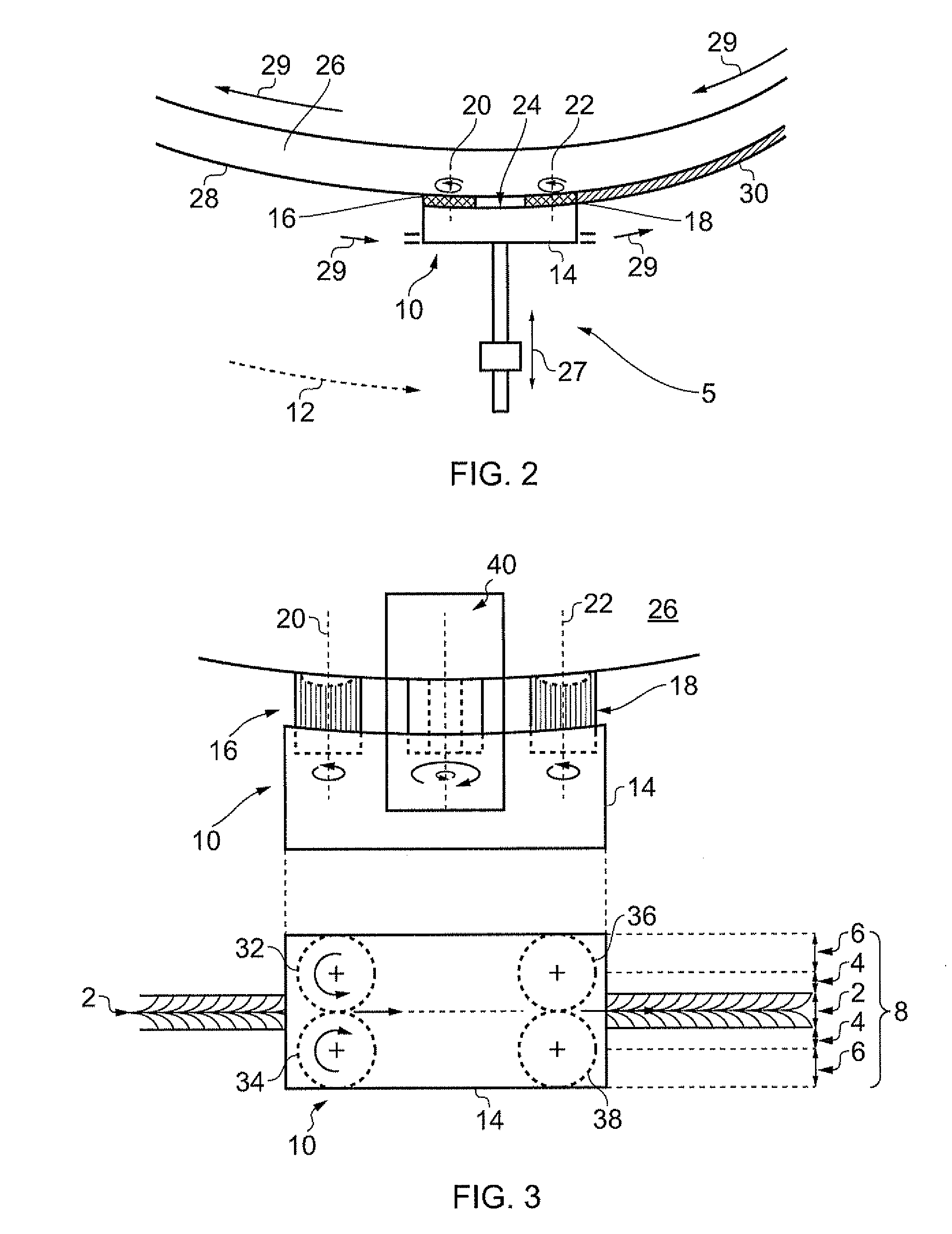
[0011]The brush head may comprise an opening, suitable to deposit or collect fluid. The apparatus may further comprise means to apply positive and / or negative pressure at the opening. The brush head may comprise at least two such openings and the apparatus may further comprise means to apply positive pressure at one opening and negative pressure at another opening. The openings may comprise two or more independent sections of a single orifice, thus allowing simultaneous deposition and collection of fluid.
[0026]According to another aspect of the present invention, there is provided a method of applying a fluid to a target region of a component using an apparatus of the first aspect of the present invention, comprising connecting a fluid supply to the fluid applicator, mounting the fluid applicator on the means for guiding the applicator along a predetermined path, bringing the applicator head into physical contact with the target region of the component, causing the applicator to be guided along the predetermined path while depositing fluid through the applicator from the fluid supply, and controlling the temperature of the fluid to be applied to the component.

Problems solved by technology

Etch tanks may have a negative environmental impact, as well as being inefficient and costly to run.
They may also produce large quantities of gas and fluid emissions.
Specialist disposal of used and waste product is required, increasing maintenance and running costs.
This often results in unsightly and inconvenient “runs” of etchant fluid straying into areas where surface etching was not required.
Swab etching is also a comparatively labour intensive method of surface etching, involving close operator contact with hazardous chemicals
However, in combination with the above methods, these practices involve high capital cost as well as increased labour and etchant response is subject to line of sight and illumation issues
A particularly difficult problem in surface etching is the removal of material from fine surface features such as are found in laser cut, machined or welded surfaces and the interfaces between such surfaces.
Weld contours, particularly in root and toe regions, present difficulties for the manipulation of line of sight based material removal processes.
Welds constitute points of material micro structural variation and it is therefore undesirable to unduly thin a weld region or to introduce additional stresses through machining.

Method used


Image

  • Apparatus and method for applying a fluid to a component
  • Apparatus and method for applying a fluid to a component
  • Apparatus and method for applying a fluid to a component

Examples


Embodiment Construction

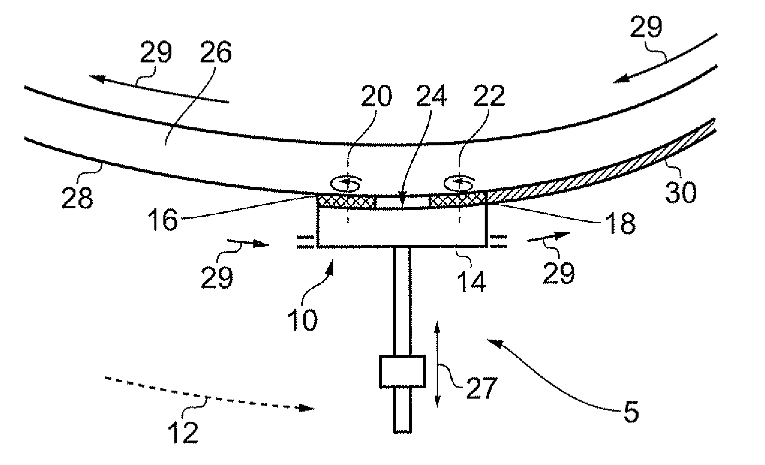
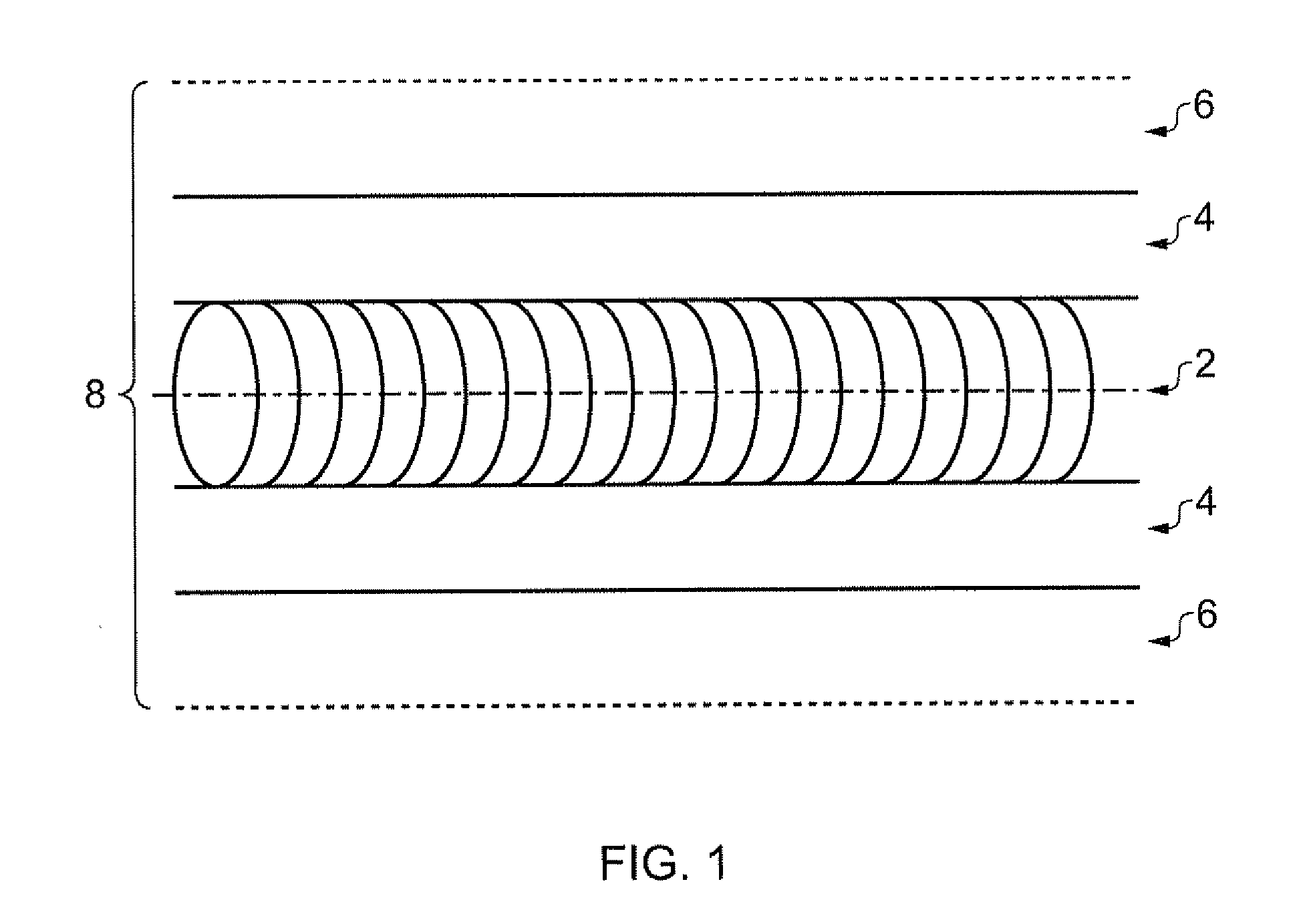
[0064]The present invention relates to an apparatus and method for applying a fluid such as a chemical etchant to a target area of a component. The following description uses the example of a weld line as a target feature of a component, an area of which may be appropriate for chemical etching. FIG. 1 illustrates a typical weld line 2, such as might be found on a metallic drum assembled using electron bean welding, around which is a heat affected zone 4. If the drum is produced from titanium, an alpha case layer can occur within the heat affected zone 4. This layer is understood to be an oxygen enriched surface layer of titanium that acts to reduce the fatigue life of the component. It is therefore desirable to remove this alpha case layer using a locally applied chemical etchant including for example Nitric, Hydrofluoric, Hydrochloric or Hydroflourosilic acids. The etchant is applied over a target area 8 that includes the weld line 2, the heat affected zone 4 and a safety zone 6. I...


PUM

PropertyMeasurementUnit
Temperatureaaaaaaaaaa
Pressureaaaaaaaaaa
Areaaaaaaaaaaa

Abstract

Apparatus for applying a fluid to a target area of a component is provided, the apparatus comprising a fluid applicator 10 and means 12, 300, 400 for guiding the fluid applicator 10 along a predetermined path with respect to the component 26; the fluid applicator 10 comprising a body 14 and an application head 50, 100, 200 mounted on the body 14 and operable in use to be brought into physical contact with the component 26.

Description

[0001]The present invention relates to an apparatus and method for applying a fluid to a component. The invention is particularly but not exclusively related to an apparatus and method for applying a chemical etchant to a target area of a component.[0002]Chemical etching is a commonly used technique for removing one or more surface layers from a metallic component. An acid, base, or other chemical etchant fluid is applied to an area of a component for a period of time and dissolves a surface layer of the component. Various methods may be used to bring the etchant fluid into contact with the component.[0003]One known method involves filling a large tank with etchant fluid and immersing a component in the fluid. Masking material may be used to prevent the etchant fluid removing a surface layer from the entirety of the component. Etch tanks may have a negative environmental impact, as well as being inefficient and costly to run. They may also produce large quantities of gas and fluid e...

Claims


Application Information

Patent Timeline
IPC IPC(8): A46B11/00
CPCA46B13/04A46B2200/20B05C1/06C23F1/08C23G3/00B05C1/027
Inventor CLARK, DANIELMILLS, DAVID W.
Owner ROLLS ROYCE PLC
Learn More