
Apparatus and control method of micro-power source for microgrid application

a micro-power source and control method technology, applied in the direction of wind energy generation, dc network circuit arrangement, energy industry, etc., can solve the problems of inability to control reactive power, fast communication cannot guarantee the preferable implementation of a micro-grid, etc., to achieve rapid steady state and smooth switch

Inactive Publication Date: 2011-10-13
GRIDON
View PDF3 Cites 66 Cited by
  • Summary
  • Abstract
  • Description
  • Claims
  • Application Information

AI Technical Summary

Benefits of technology

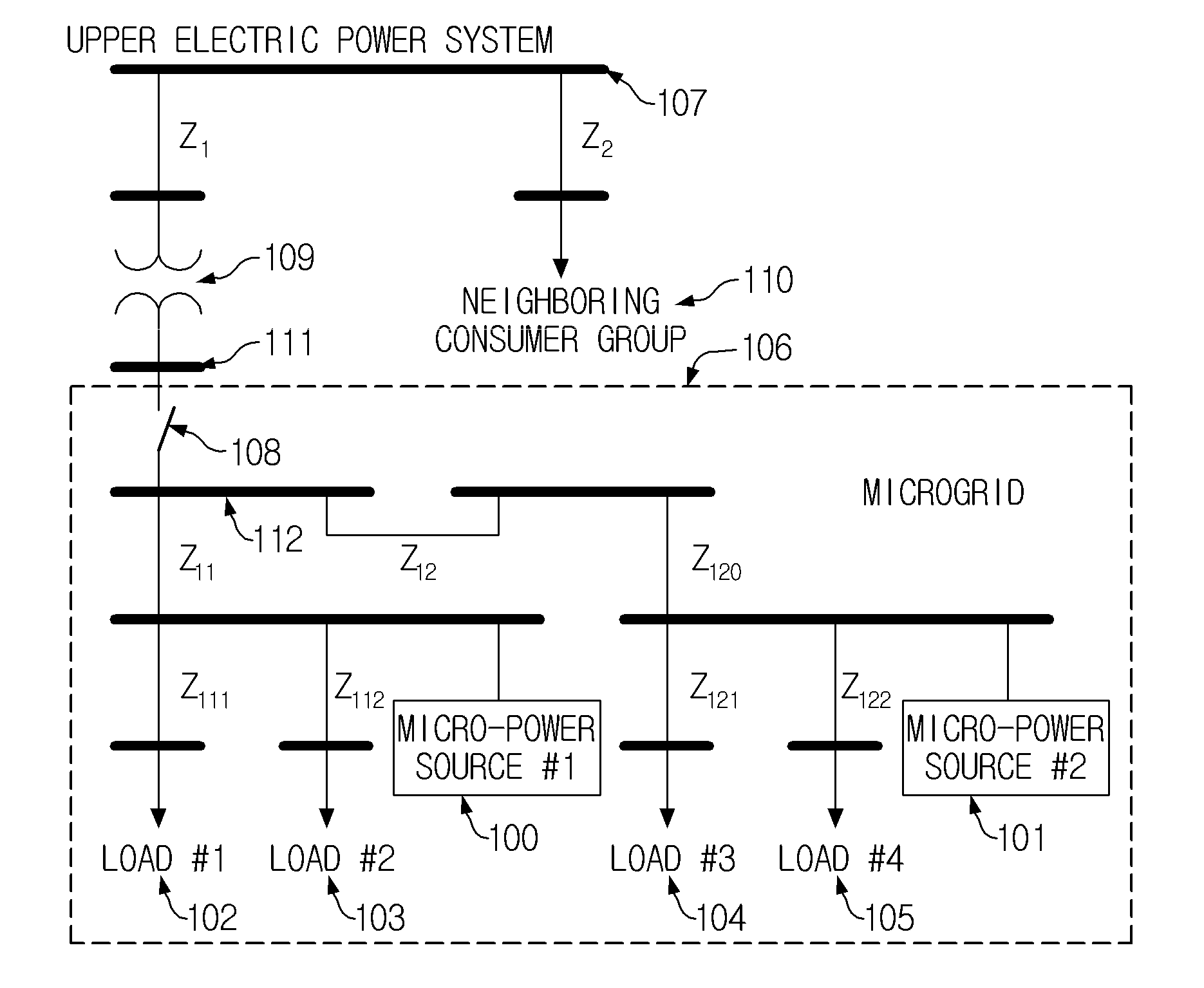
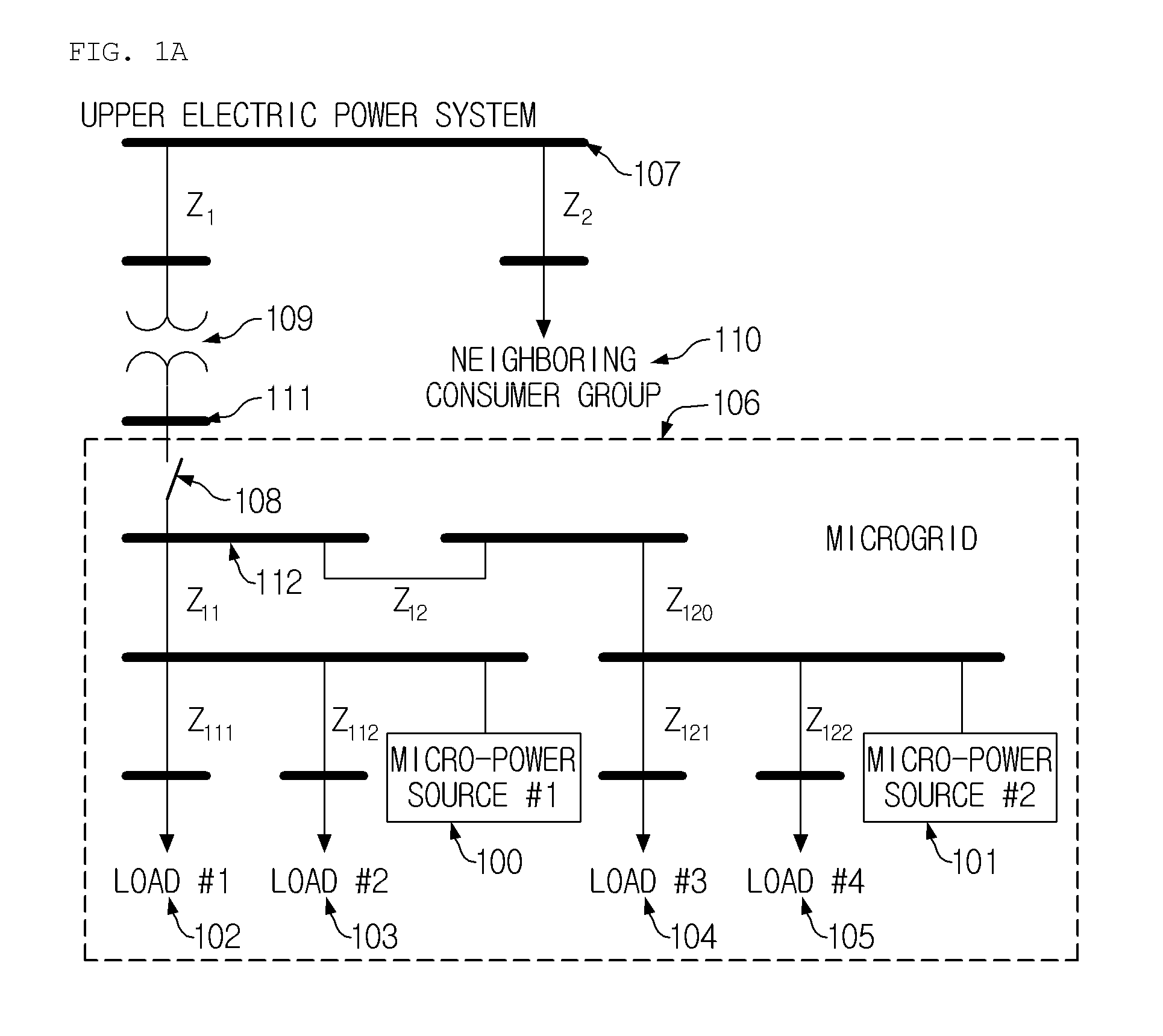
[0051]Therefore, in order to preferably implement a microgrid, a second problem to be solved by the present invention is to allow the micro-power sources 100 and 101 to synchronize the voltage of the microgrid with the voltage of the upper electric power system 107 without performing fast communication with the interface switch 108, and smoothly reconnect the microgrid to the upper electric power system 107 after the completion of synchronization.
[0054]Accordingly, the present invention has been made considering the above problems occurring in the prior art, and the object of the present invention is to provide the construction and control structure of a micro-power source and methods of controlling the active and reactive power of the micro-power source which can improve power quality.
[0057]Since the micro-power source according to the present invention includes the interface switch, it does not require fast communication, and thus can synchronize the voltage of the microgrid with the voltage of an upper electric power system. Further, since the micro-power source control device directly controls the interface switch, smooth reconnection between the microgrid and the upper electric power system can be performed. Furthermore, the improved controller of FIG. 9 based on the control method for the micro-power source according to the present invention feeds the output of a deactivated control block forward to the output of a control block which is activated after reconnection, thus causing the output voltage reference value of the micro-power source to continue at the time point of reconnection. As a result, it is possible for the microgrid to more rapidly reach a steady state, thus contributing to the smooth reconnection of the microgrid.

Problems solved by technology

However, fast communication cannot guarantee the preferable implementation of a microgrid due to the problem of reliability.
However, the micro-power source using the controller of FIG. 8 cannot control reactive power and merely controls voltage using droop characteristics in a grid-connected operation.

Method used


Image

  • Apparatus and control method of micro-power source for microgrid application
  • Apparatus and control method of micro-power source for microgrid application
  • Apparatus and control method of micro-power source for microgrid application

Examples


Embodiment Construction

[0080]Hereinafter, embodiments of the present invention will be described in detail with reference to the attached drawings. However, the present invention is not limited or restricted to those embodiments.

[0081]Reference now should be made to the drawings, in which the same reference numerals are used throughout the different drawings to designate the same or similar components.

[0082]FIG. 12A is a diagram showing the construction of a microgrid 1201 implemented using a micro-power source 1200 according to an embodiment of the present invention.

[0083]Referring to FIG. 12A, the microgrid 1201 according to an embodiment of the present invention includes the micro-power source 1200 and the remainder 1202 of the microgrid 1201. The micro-power source 1200 includes a third bus 1205 connected to an upper electric power system 1204 via a transformer 1203, a first interface switch (Interface Switch: IS) 1212, a second bus 1206 connected to the third bus 1205 via the IS 1212, a second interf...


PUM


Abstract

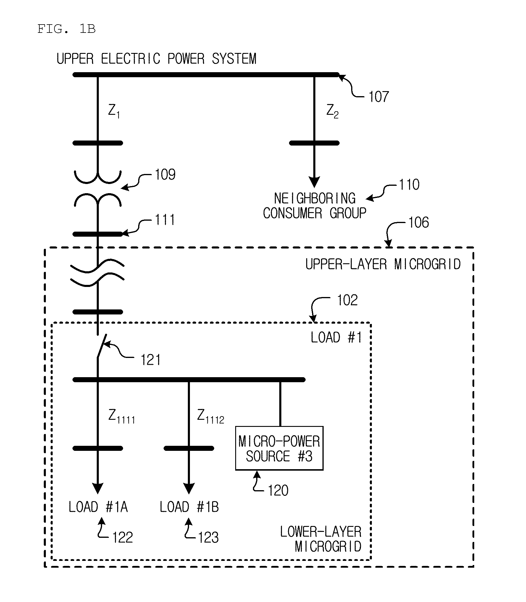
The present invention relates to a micro-power source for successfully implementing a microgrid and to a control method for realizing smooth reconnection between the microgrid and an upper electric power system and smooth switching between the control modes of the micro-power source. A micro-power source sectionalizes an electric power system into an upper electric power system and a lower electric power system, and enables the lower electric power system to be independently operated in an island mode and to smoothly switch between a grid-connected mode and the island mode. As a result, a hierarchical microgrid is implemented with sectionalized sub-microgrids. One of the merits of the hierarchical microgrid is that each consumer group can be supplied with high quality power regardless of the power quality of the other consumer groups, and various types of services independently.

Description

BACKGROUND OF THE INVENTION[0001]1. Field of the Invention[0002]The present invention relates, in general, to a micro-power source and a control method for the micro-power source, and, more particularly, to the construction and control method of a micro-power source for successfully implementing a microgrid and to a control method for realizing smooth reconnection between the microgrid and an upper electric power system, and smooth switching between the control modes of the micro-power source.[0003]2. Description of the Related Art[0004]Recently, various types of micro-power sources such as photovoltaics, fuel cells, micro turbines, energy storage devices, and diesel engine power generation have been frequently introduced to the electric power due to problems related to the location of power stations, investment in the construction of power transmission and distribution lines, environment, and etc.[0005]Current regulation of utilities limits island operation of the micro-power sourc...

Claims


Application Information

Patent Timeline
IPC IPC(8): H02J3/08
CPCH02J3/381H02J3/383H02J3/386H02J3/382H02J2003/388Y02E10/563Y02E10/763H02J3/387Y02P80/14H02J3/388H02J2300/10H02J2300/30H02J2300/28H02J2300/20H02J2300/24Y02E10/56Y02E10/76
Inventor SON, KWANG MYOUNGLEE, KYE BYUNG
Owner GRIDON
Learn More