Blood vessel display device

a display device and blood vessel technology, applied in the field of blood vessel display devices, can solve the problems of difficult to obtain blood vessels, difficult to identify visually, and defocusing

Inactive Publication Date: 2011-10-06
SEIKO EPSON CORP
View PDF8 Cites 10 Cited by
  • Summary
  • Abstract
  • Description
  • Claims
  • Application Information

AI Technical Summary

Benefits of technology

[0013]In this case, the device configuration of the blood vessel display device becomes simple.
[0015]In this case, the device configuration of the light scanning section becomes simple, and excellent laser light scanning characteristics can be realized.
[0017]In this case, the device configuration of the blood vessel display device becomes simple. In addition, since the laser light for display and the laser light for detection scan the irradiated part using the same light scanning section, a blood vessel image positioned correctly without deviation can be depicted on the irradiated part scanned by the laser light for detection.
[0019]Near-infrared laser light has a characteristic of being absorbed by hemoglobin contained in the blood flowing through the blood vessel. Accordingly, using such a characteristic, it is possible to more reliably detect a blood vessel present in the superficial layer of the irradiated part.
[0023]In this case, since a target part can be easily checked, it becomes easier to perform various medical treatments.
[0025]In this case, it becomes easier to obtain a blood vessel when giving an injection (when inserting an injection needle beneath the skin).

Problems solved by technology

However, there are some patients whose blood vessels are difficult to identify visually, for example, a child or a person with thick subcutaneous fat.
In such a case, it is very difficult to obtain the blood vessels.
For this reason, when an image is displayed on the body tissue surface using a DLP projector or the like, a problem also occurs in which defocusing occurs and an image is blurred accordingly.
That is, a device in the related art has a problem in that it is not possible to display a blood vessel image, which is clear and has no positional deviation from the actual blood vessels, on the body tissue surface.

Method used


Image

  • Blood vessel display device
  • Blood vessel display device
  • Blood vessel display device

Examples


first embodiment

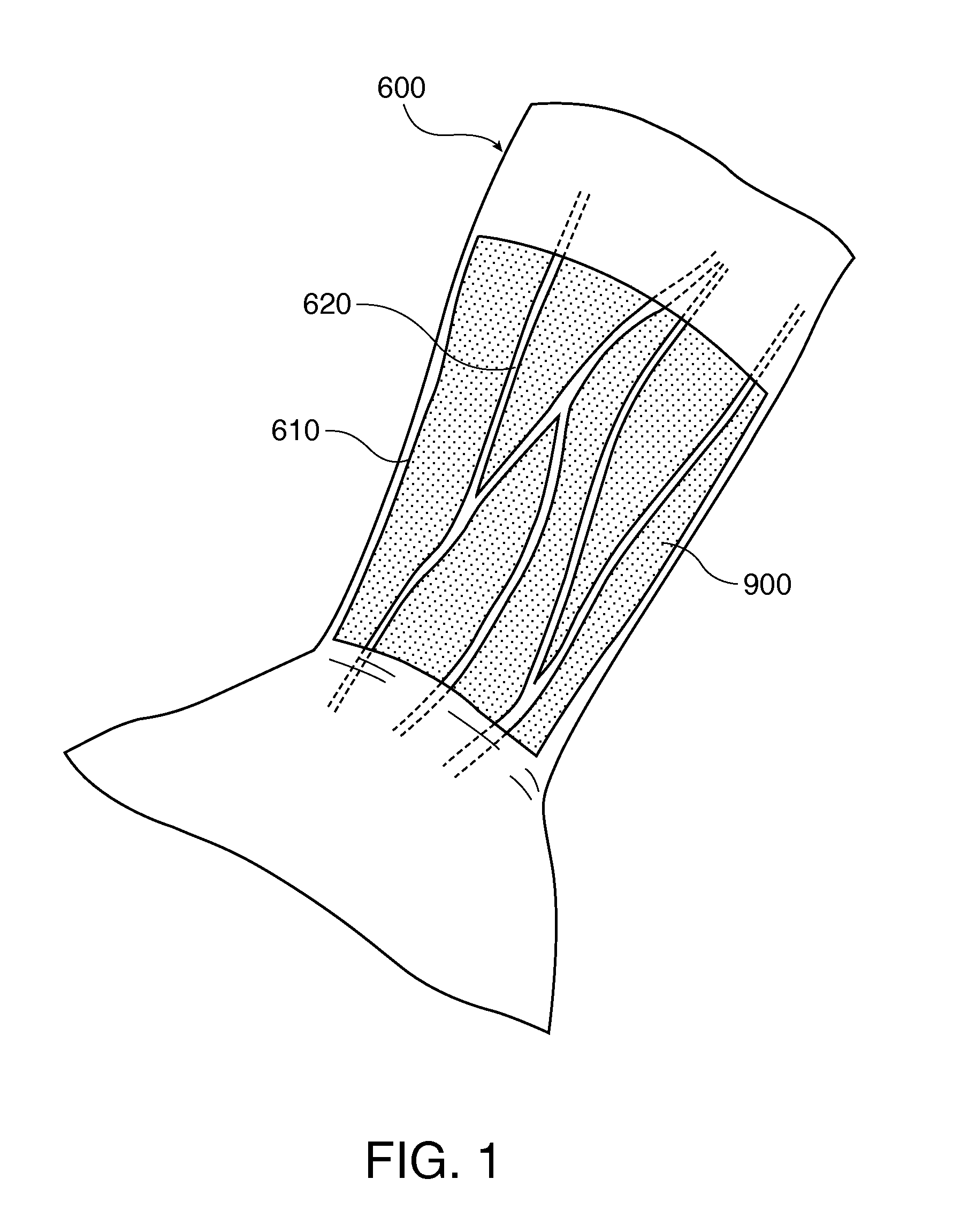
[0036]First, a blood vessel display device according to a first embodiment of the invention will be described.

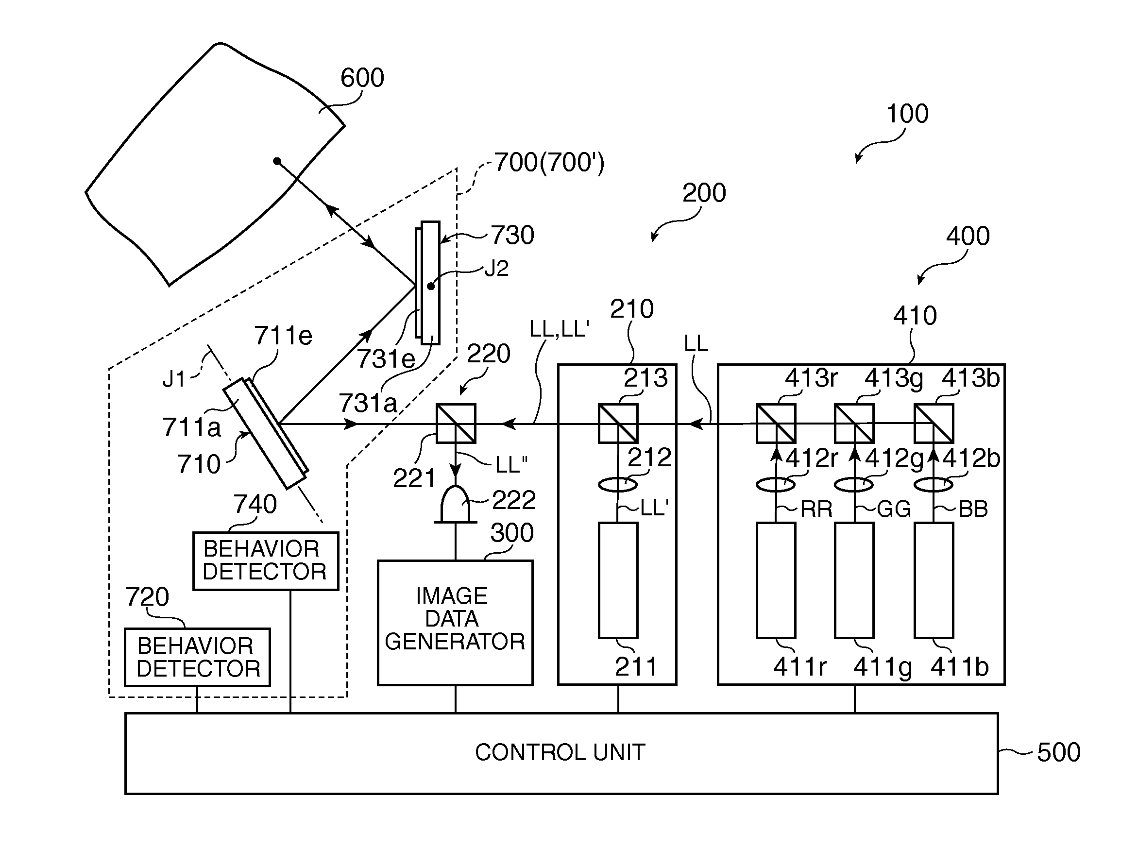
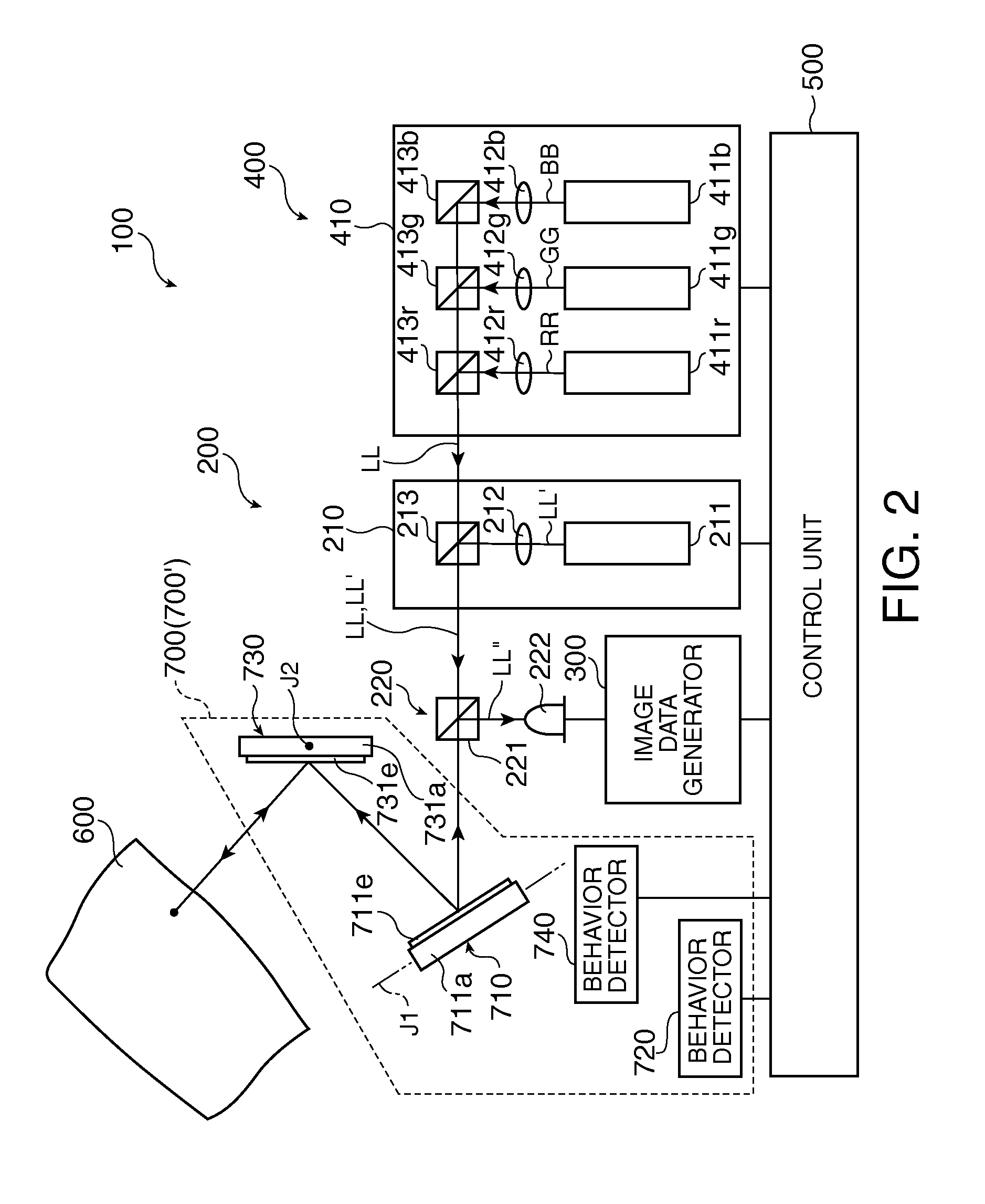
[0037]FIG. 1 is a view showing an image displayed by the blood vessel display device according to the first embodiment of the invention. FIG. 2 is a schematic view showing the blood vessel display device according to the first embodiment of the invention. FIG. 3 is a perspective view showing the partial cross section of an optical scanner provided in the blood vessel display device shown in FIG. 2. FIGS. 4A and 4B are cross-sectional views for explaining the driving of the optical scanner shown in FIG. 3. Moreover, in the following explanation, an upper side, a lower side, a left side, and a right side in FIGS. 3, 4A, and 4B are called “top”, “bottom”, “left”, and “right”, respectively, for the sake of convenience.

[0038]A blood vessel display device 100 is a device which visualizes a blood vessel (especially a vein) present in a superficial layer of body tissue. Such a blood...

second embodiment

[0101]Next, a blood vessel display device according to a second embodiment of the invention will be described.

[0102]FIG. 5 is a schematic view showing the blood vessel display device according to the second embodiment of the invention. FIGS. 6A to 6C are views showing an example of an image displayed by a display unit shown in FIG. 5.

[0103]Hereinafter, a blood vessel display device 100A according to the second embodiment will be described focusing on a point of difference from the above blood vessel display device 100 according to the first embodiment, and explanations of the same subjects will be omitted.

[0104]The blood vessel display device 100A according to the second embodiment is almost the same as the blood vessel display device according to the first embodiment except that a point determining section 800 is provided and an image displayed on the irradiated part 610 is different. In addition, the same components as in the first embodiment described above are denoted by the sam...


PUM


Abstract

A blood vessel display device includes: a detection unit that scans body tissue with laser light for detection and detects reflected light from an irradiated part of the body tissue to which the laser light for detection has been irradiated; an image data generating unit that detects a surface shape of the irradiated part and the arrangement of blood vessels, which are present in a superficial layer of the irradiated part, on the basis of a detection result of the detection unit and generates image data of an image for visualizing the blood vessels displayed on the irradiated part; and a display unit that displays an image for visualizing the blood vessels on the irradiated part by scanning the irradiated part with laser light for display on the basis of the image data generated by the image data generating unit.

Description

BACKGROUND[0001]1. Technical Field[0002]The present invention relates to a blood vessel display device.[0003]2. Related Art[0004]In the medical field, for example, when a doctor or the like gives a patient an injection in his or her arm, the doctor or the like finds a blood vessel in the superficial layer and inserts an injection needle beneath the skin tissue. In this case, if a doctor can visually identify a blood vessel, the probability that the blood vessel will be obtained is high. However, there are some patients whose blood vessels are difficult to identify visually, for example, a child or a person with thick subcutaneous fat. In such a case, it is very difficult to obtain the blood vessels.[0005]In recent years, therefore, a device (“VEINVIEWER” made by Luminetx) which visualizes blood vessels by displaying blood vessel image data, which is acquired by a known vein identification technology, in real time on the body tissue surface (for example, the back of a hand) using a D...

Claims


Application Information

Patent Timeline
Patent Type & Authority Applications(United States)
IPC IPC(8): A61B6/00
CPCA61B5/0064A61B5/489
Inventor MURATA, AKIHIROTAKEDA, TAKASHI
Owner SEIKO EPSON CORP
Why Eureka
Try Eureka