
Cooling arrangement for a luminaire

a cooling arrangement and luminaire technology, applied in the direction of spark plugs, corona discharge, lighting and heating apparatus, etc., can solve the problems of high heat load of high-power leds, fan consumption of extra power, and bulky type of cooling arrangement, so as to reduce the need for heat sinks, and similar or better performance

Inactive Publication Date: 2011-10-06
SIGNIFY HLDG BV +1
View PDF6 Cites 1 Cited by
  • Summary
  • Abstract
  • Description
  • Claims
  • Application Information

AI Technical Summary

Benefits of technology

[0009]By means of this aspect of the present invention it may be possible to provide cooling of a device, such as a luminaire, having similar or better performances than a conventional heat sink and fan system, but with a smaller size and weight as well as being able to operate silently. Due to the possibility of generating a concentrated airflow close to the heat source, e.g. light source of the luminaire, it may be possible to also reduce the need for heat sinks, fans, thermal pastes, etc. Preferably, the source electrode is a corona electrode. Accordingly, the electron discharge is a corona discharge generating air ions.
[0010]The distance between the source electrode and at least one of the first and the second target electrodes should be more than the distance at which electrical breakdown occurs. In an embodiment, the potential difference between the source electrode, e.g. the corona electrode, and at least one of the first and the second target electrodes is sufficient for ionization of molecules in the surrounding air at the corona electrode and subsequent air flow from said electrode towards the target electrode. Preferably, the cooling arrangement is driven in a low voltage operation, thereby increasing the possibility to provide a safe and reliable arrangement.
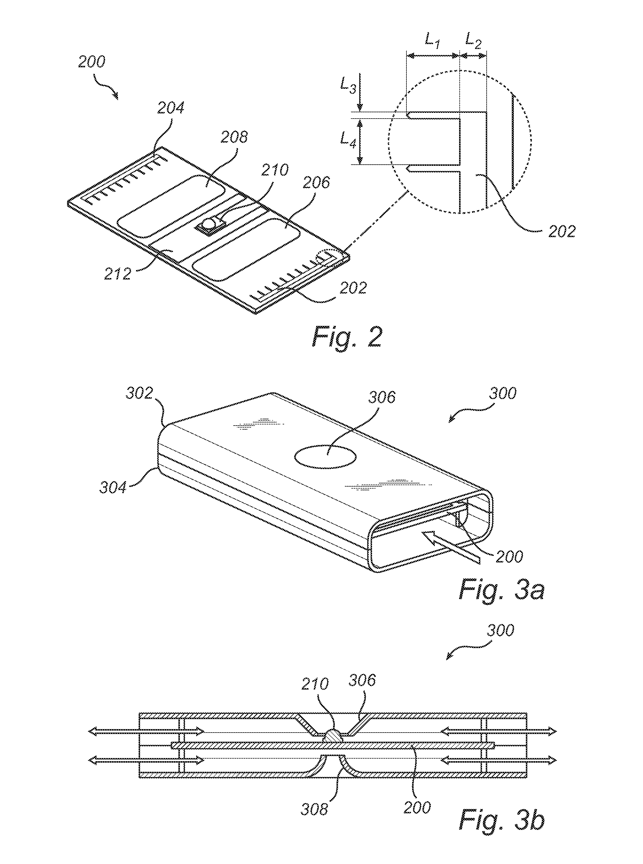
[0011]It is possible to in different ways arrange the source electrode and the first and the second target electrodes. In one embodiment the electrodes are arranged on a carrying member, without limitation for example represented by a hollow structure having a shell. In such a case the electrodes may be coated on the inside of hollow structure. For example, the source electrode and at least one of the first and the second target electrodes may be arranged on the inside of the shell of the hollow structure (e.g. as a coating on the inside of the shell). In another embodiment the source electrode and at least one of the first and the second target electrodes may instead (or also) be arranged onto a substrate (in this case representing the carrying member), for example fixated between a first and a second portion of the hollow structure. Preferably, the source electrode, the first and the second target electrodes and / or the inner surface of the shell may be coated with a noble metal, which will reduce and possibly break down ozone that may be produced at the source electrode.
[0012]In an embodiment, the hollow structure comprises an inflow portion and an outflow portion. Also, the hollow structure may be arranged such that it comprises at least one opening having a cone shaped air inlet towards the inside of the hollow structure for providing a Venturi effect. The Venturi effect in relation to the present invention will be further discussed below. Preferably, the opening is arranged in close connection with the device that needs cooling, such as for example a light source.
[0016]By means of this aspect of the present invention it is, in a similar and analogue way as described above with reference to the first aspect of the invention, possible to provide cooling of a device, such as a luminaire, having similar or better performances than a conventional heat sink and fan system, but with a smaller size and weight as well as being able to operate silently. Due to the possibility of generating a concentrated airflow close to the heat source, e.g. light source of the luminaire, it may be possible to also reduce the need for heat sinks, fans, thermal pastes, etc. Additionally, this aspect also provides for the possibility to use different types of carrying members, such as a hollow structure having a shell or a substrate such as for example a PCB. Other implementation specific solutions are of course possible.

Problems solved by technology

However, the high power LEDs suffers from a high thermal load when used in traditional lighting applications.
Important parameters of the LED such as efficiency, lifetime, and color are very sensitive to the temperature of the LED, thus making thermal management a key issue in LED lighting applications, especially in adjustable color lighting system where color control is essential for providing a useful application.
This type of cooling arrangement is often bulky since the heat sink needs to be quite large to provide the necessary cooling to the LED.
However, the fan will consume extra power and will often add unwanted noise to the lighting arrangement.
Additionally, fans are subject to wear, limiting their lifetime and reliability.
Furthermore, the large bulky structure hampers the design of elegant and sleek lighting applications.
However, not even the cooling arrangement of the cited patent application will solve the problem of getting rid of the bulky fan.

Method used


Image

  • Cooling arrangement for a luminaire
  • Cooling arrangement for a luminaire
  • Cooling arrangement for a luminaire

Examples


Embodiment Construction

[0023]The present invention will now be described more fully hereinafter with reference to the accompanying drawings, in which currently preferred embodiments of the invention are shown. This invention may, however, be embodied in many different forms and should not be construed as limited to the embodiments set forth herein; rather, these embodiments are provided for thoroughness and completeness, and fully convey the scope of the invention to the skilled addressee. Like reference characters refer to like elements throughout.

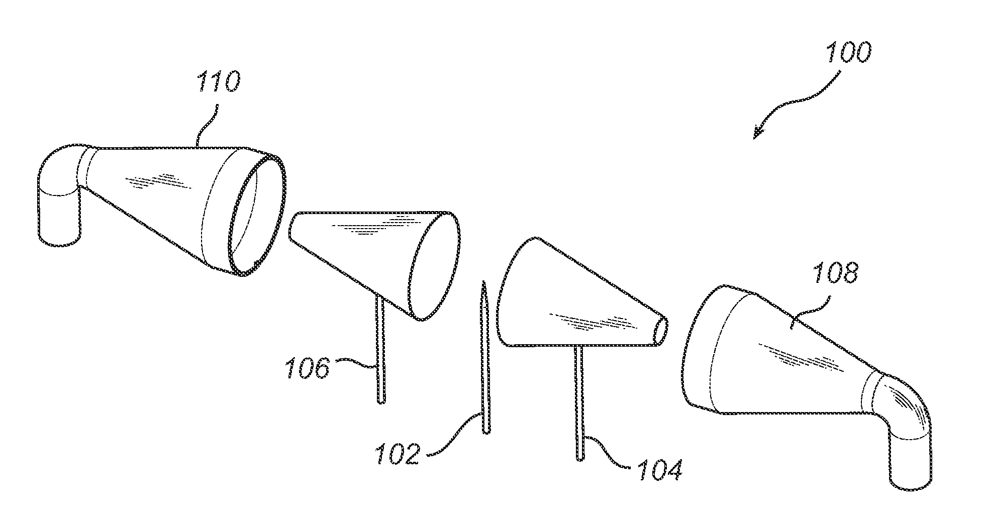
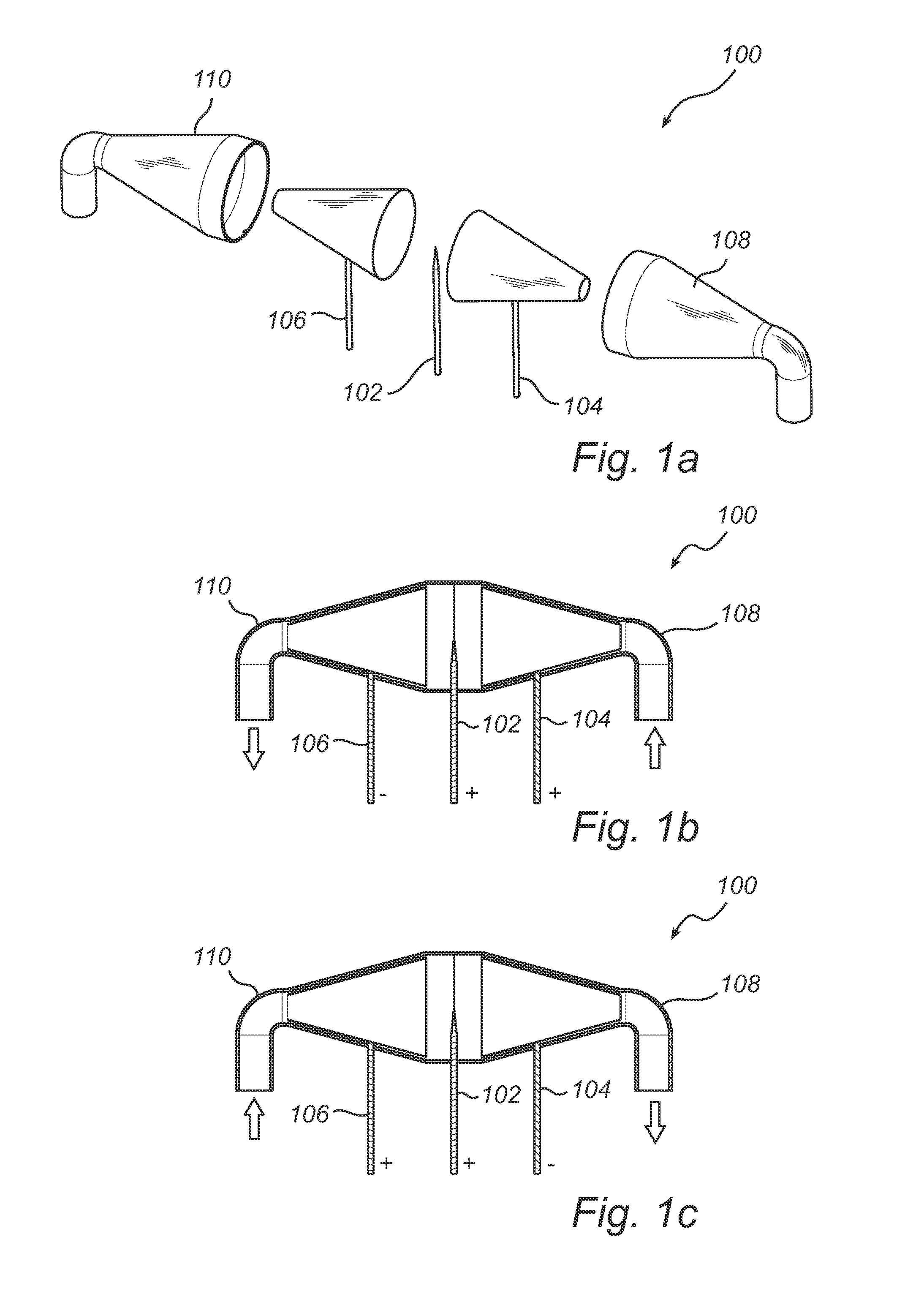
[0024]Referring now to the drawings and to FIG. 1 in particular, there is depicted a schematic illustration of a cooling arrangement according to a currently preferred embodiment of the present invention. FIG. 1a shows the separate part of the cooling arrangement 100, comprising a source electrode in the form of a corona electrode 102, a first target electrode 104 and a second target electrode 106. Additionally, the cooling arrangement 100 comprises a first and...


PUM


Abstract

A cooling arrangement comprising a source electrode, a first and a second target electrode arranged at a distance from the source electrode and control circuitry for controlling a voltage being applied between the source electrode and at least one of the first and the second target electrodes. The voltage is controlled such that an airflow resulting from a potential difference between the source electrode and at least one of the first and the second target electrodes is arranged to have alternating directions. By means of the invention it may be possible to provide cooling of a device having similar or better performances than a conventional heat sink and fan system, but with a smaller size and weight as well as being silent.

Description

TECHNICAL FIELD[0001]The present invention relates to an arrangement for providing cooling of a device, specifically to a luminaire comprising such a cooling arrangement. The present invention also relates to a corresponding method.BACKGROUND OF THE INVENTION[0002]Recently, much progress has been made in increasing the brightness of light emitting diodes (LEDs). As a result, LEDs have become sufficiently bright and inexpensive to serve as a light source in for example illumination arrangements such as lamps with adjustable color. By mixing differently colored LEDs any number of colors can be generated, e.g. white. An adjustable color lighting system is typically constructed by using a number of primary colors, and in one example, the three primaries red, green and blue are used. The color of the generated light is determined by which of the LEDs that are used, as well as by the mixing ratios. To generate “white”, all three LEDs have to be turned on.[0003]In for example industrial an...

Claims


Application Information

Patent Timeline
Patent Type & Authority Applications(United States)
IPC IPC(8): F21V29/00F28F7/00
CPCH01T23/00F21Y2101/02F21V29/83H01T19/00F21V29/63H01T13/50F21Y2115/10F21V29/00
Inventor GIELEN, VINCENT S. D.DE WINTER, ARJANTREUENIET, THEODOOR C.VAN DER VEEKEN, RENATUS W. C.REBERGEN, JOHANNES A.MANDERS, GODFRIED C. G. M.
Owner SIGNIFY HLDG BV
Learn More