Energy storage device and manufacturing method thereof
a technology of energy storage and manufacturing method, which is applied in the direction of cell components, final product manufacturing, sustainable manufacturing/processing, etc., can solve the problems of difficult to detect the remaining capacity of the electrode potential, the electric circuit that becomes a load may be broken, and the electric circuit may malfunction, so as to achieve stable charge and discharge characteristics, easy to detect remaining capacity, and stable charge
- Summary
- Abstract
- Description
- Claims
- Application Information
AI Technical Summary
Benefits of technology
Problems solved by technology
Method used
Image

Examples
embodiment 1
[0027]In this embodiment, charge and discharge characteristics of an energy storage device is described.
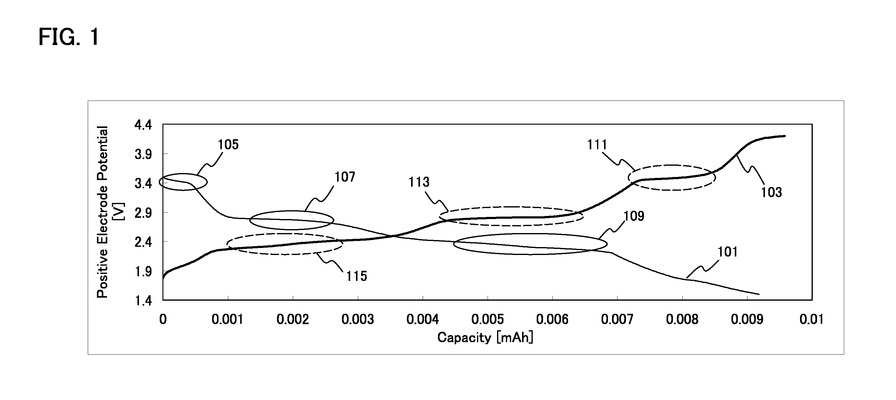
[0028]FIG. 1 shows charge and discharge characteristics of a positive electrode in an energy storage device, and reference numeral 101 denotes a discharging curve, and reference numeral 103 denotes a charging curve. The horizontal axis and the vertical axis indicate capacity and positive electrode potential, respectively.
[0029]In FIG. 1, the discharging curve 101 has flat portions of the potential (hereinafter also referred to as plateaus); thus, stable voltage can be supplied. Further, in the example in FIG. 1, the discharging curve 101 has plateaus in three steps (a plateau 105, a plateau 107, and a plateau 109).
[0030]The positive electrode potential of each plateau in the discharging curve 101 is as follows: the potential Vmax of the plateau 105 is 3.5V; the potential Vmid of the plateau 107 is 2.9V; and the potential Vmin of the plateau 109 is 2.4V.
[0031]Since the discharging ...
embodiment 2
[0043]In this embodiment, an example of a method for manufacturing an energy storage device which can achieve charge and discharge characteristics as described in Embodiment 1 is illustrated.
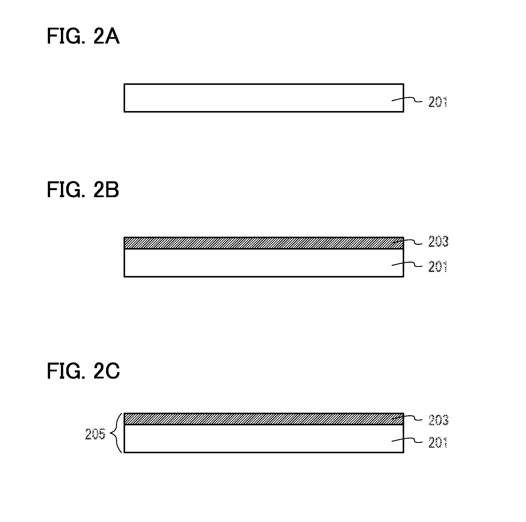
[0044]FIGS. 2A to 2C illustrate an example of a method for manufacturing a positive electrode of a lithium secondary battery.
[0045]First, the current collector 201 is prepared (FIG. 2A).
[0046]There is no particular limitation on a material used for the current collector 201; however, a material having high conductivity such as platinum, aluminum, copper, or titanium can be used. In this embodiment, titanium is used.
[0047]Next, a film 203 including an active material is formed over the current collector 201 (FIG. 2B).
[0048]Lithium oxide is preferably used for a material for the active material included in the film 203 including an active material. Lithium has high ionization tendency and a small atomic radius, whereby injection into and extraction from a positive electrode can be performed stably...
embodiment 3
[0058]In this embodiment, an example of the structure of the energy storage device is described.
[0059]An example of the structure of the positive electrode used in the energy storage device is described with reference to FIG. 2C.
[0060]The positive electrode 205 includes the current collector 201 and the film 203 including an active material formed over the current collector 201.
[0061]The material described in Embodiment 2 can be used as a material for the current collector 201. In this embodiment, titanium is used.
[0062]The material described in Embodiment 2 can be used for a material for the active material. In this embodiment, lithium iron phosphate with a thickness of 100 nm is used.
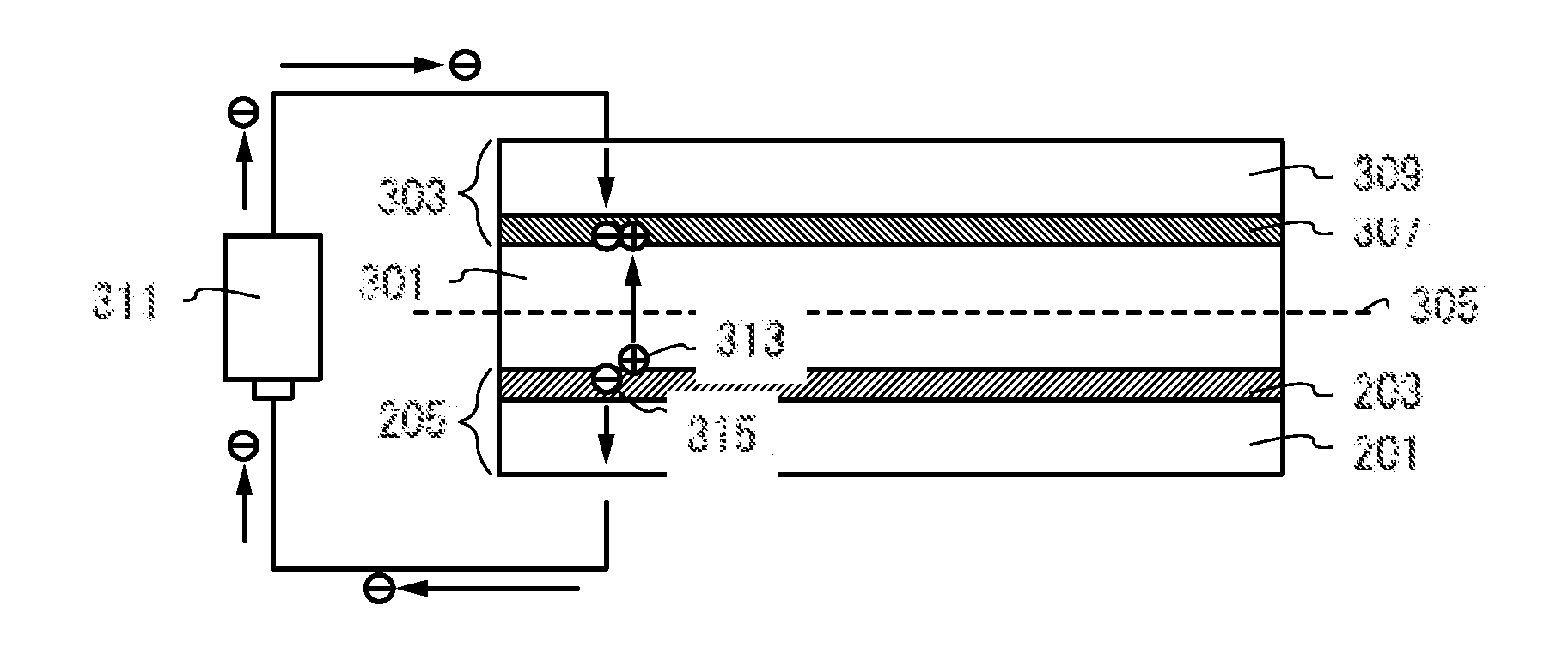
[0063]An example of the structure of the energy storage device using the above positive electrode is described.
[0064]FIGS. 3A to 3C are an example of the energy storage device, which includes the positive electrode 205, a negative electrode 303 provided so as to face the positive electrode 205, and an...
PUM
| Property | Measurement | Unit |
|---|---|---|
| positive electrode potential | aaaaa | aaaaa |
| thickness | aaaaa | aaaaa |
| thickness | aaaaa | aaaaa |
Abstract
Description
Claims
Application Information
 - R&D
- Intellectual Property
- Life Sciences
- Materials
- Tech Scout
- Unparalleled Data Quality
- Higher Quality Content
- 60% Fewer Hallucinations
Browse by: Latest US Patents, China's latest patents, Technical Efficacy Thesaurus, Application Domain, Technology Topic, Popular Technical Reports.
© 2025 PatSnap. All rights reserved.Legal|Privacy policy|Modern Slavery Act Transparency Statement|Sitemap|About US| Contact US: help@patsnap.com