
Mcfc power generation system and method for operating same

a technology of power generation system and gas turbine, which is applied in the direction of electrochemical generator, fuel cell, fuel cell, etc., can solve the problems of power generation efficiency decline, and achieve the effect of reducing eliminating fuel humidifier, and no, or minimizing the amount of external supply of fuel gas

Inactive Publication Date: 2011-09-15
TOKYO GAS CO LTD
View PDF1 Cites 69 Cited by
  • Summary
  • Abstract
  • Description
  • Claims
  • Application Information

AI Technical Summary

Benefits of technology

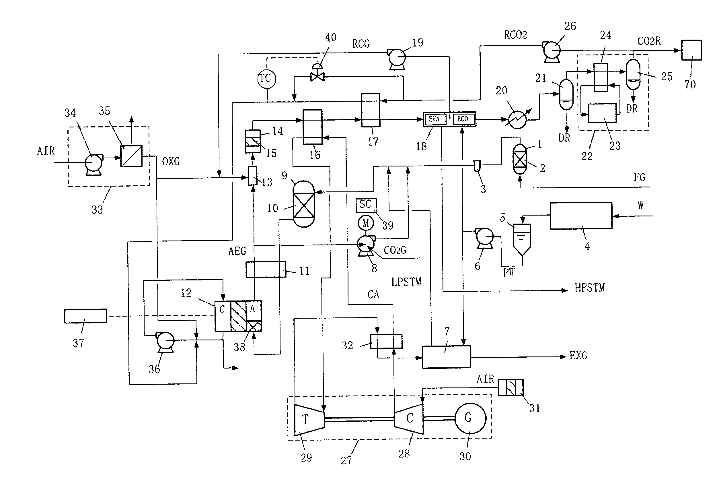
[0055](1) According to the composition of the above-described present invention, the system comprises a cathode gas circulation system, wherein cathode gas is circulated by a cathode gas circulation blower and forms a closed loop; oxygen consumed by the power generation reaction is supplied by the oxygen supplying plant, and CO2 is supplied by recycled CO2, and thus, the necessary amount and composition of cathode circulation gas is maintained, and there is basically no exhaust from the cathode circulation system. Therefore, it may be said that the present power generation facility is a power generation facility with substantially no, or minimized, atmospheric release of CO2.
[0056](2) On the other hand, since only CO2 remains by combusting combustible components in the anode exhaust under oxygen, cooling and removing water, part of such CO2 is recycled to the cathode, while the remainder is mostly collected as high c

Problems solved by technology

Although the use of oxygen can be a factor in increasing power generation efficiency in MCFC, since a gas turbine is decided by the flow rate, the entrance temperature, and the pressure ratio that flows through the gas turbine, there is no particular advantage in using oxygen, and the consumption power for the oxygen plant corresponding to the gas turbine becomes a factor that decreases power generation efficiency.

Method used


Image

  • Mcfc power generation system and method for operating same
  • Mcfc power generation system and method for operating same
  • Mcfc power generation system and method for operating same

Examples


example 1

[0111]FIG. 6 describes the cathode gas circulation system part of FIG. 5 in further detail.

[0112]It is necessary to supply CO2 and O2 which are consumed by the power generation reaction (CO2+1 / 2O2+2e−->CO32−) at the cathode, and purged. The reaction amount may be calculated from the direct-current of the fuel cell, and the purged amount may be checked by flow control valve 53. O2 from the oxygen plant established in the exterior of the MCFC power generation plant, is controlled by the flow control valve 51, and is supplied at a temperature near normal temperature. CO2 is supplied to the cathode gas circulation system by controlling the flow rate of recycled CO2 (RCO2), obtained by combustion of anode exhaust under oxygen, cooling, and water-extraction, with a flow control valve 52, and by controlling the temperature with a temperature control valve 40 built in a CO2 heater 36. Since the temperature of the gas passing through the cathode is higher at the outlet than the inlet due to ...

example 2

[0117]Voltage deteriorates with operation time in every fuel cell. In general, the life of a fuel cell is defined as the point at which cell voltage deteriorates 10%. If operation time per year is assumed to be 8000 hours and the cell life is five years, that is 40000 hours, deterioration occurs 1% each per half a year, and the output of fuel cell and power generation efficiency will fall 1% per half a year, as well, in proportion to the voltage. However, according to the present invention, CO2 and O2 concentration at the cathode can be gradually raised, in correspondence to the deterioration of the fuel cell, thereby keeping the voltage of the fuel cell constant.

[0118]FIG. 10 shows the data for voltage fixed operation. This figure is an example of CO2 and O2 concentration change for maintaining the same performance as that of standard operating conditions for five years; by applying such operation, the output and power generation efficiency of the fuel cell can be increased relativ...

example 3

[0119]FIG. 7 is a detailed drawing that describes the fuel gas supply system in FIG. 5; the anode outlet is connected to a fuel heater 11 the temperature of the outlet gas from pre-convertor 9 is heated, utilizing the anode exhaust as a heat source, to a temperature close to the operation temperature of fuel gas. The anode exhaust, whose temperature then decreases, is divided into two lines, one of which is connected to an anode exhaust circulation blower, and the blower outlet gas is mixed with externally-supplied fuel gas, such as urban gas. Fuel gas, such as urban gas, is supplied by adjusting its flow rate with a flow control valve 56. Subsequently, it is mixed with steam for reforming such urban gas, and the like. Steam is supplied by adjusting its flow rate with a flow control valve 57.

[0120]Although FIG. 7 indicates that mixing occurs in the piping, mixing may be performed by methods such as one that uses a mixer, or one where mixing is performed inside a pre-convertor 9, and...


PUM


Abstract

Disclosed is an MCFC power generation system and a method for operating the same enabling significant reduction of CO2 emission or substantially zero CO2 emission by minimizing the equipment added to a general power generation facility to a minimum, enabling both high power generation efficiency and high heat recovery efficiency, enabling adjustment of the voltage and output of the fuel cell in a certain range by adjusting the cathode gas composition, enabling great variation of the ratio between the heat and electricity, and thereby enabling variable thermoelectric operation. The MCFC generation system includes a cathode gas circulation system in which the cathode gas is circulated by a cathode gas recycle blower, and a closed loop is formed. Oxygen consumed by power generation is supplied from an oxygen supply plant, and CO2 is supplied from recycled CO2. Combustible components in anode exhaust are burned with oxygen, the resultant gas is cooled, and water is removed. The fuel gases in the anode exhaust is recycled.

Description

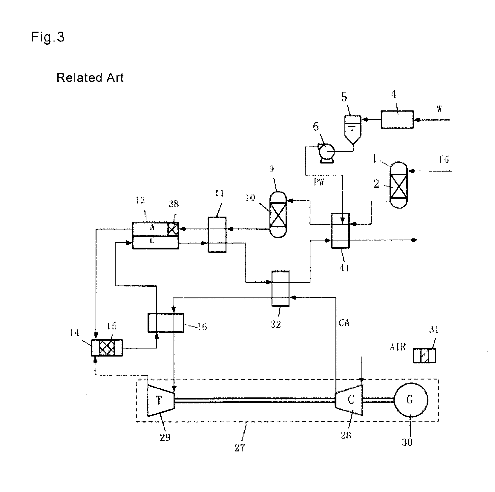
TECHNICAL FIELD[0001]The present invention belongs to the field of energy transduction equipment, and is related to a fuel cell which directly transforms chemical energy that fuel gas contains into electricity. In particular, the present invention relates to an MCFC gas-turbine hybrid system that increases the power generation efficiency of molten carbonate fuel cells (MCFC), makes recovery of CO2 easy, and further enables operations such as thermoelectric conversion, gives flexibility to a system so as to enable free adjustment of cathode gas composition, thereby contributing to effective use of energy resources and improvement of earth environment, and a method of operating the same.[0002]Hereinafter, in this application, a MCFC-gas turbine hybrid system is simply described as “MCFC power generation system.”BACKGROUND ART[0003]FIG. 3 is a configuration diagram of conventional MCFC power generation system (MCFC-gas turbine hybrid system).[0004]A fuel gas FG, such as urban gas, is l...

Claims


Application Information

Patent Timeline
IPC IPC(8): H01M8/04H01M8/06
CPCH01M8/04014H01M8/04097H01M8/04111H01M8/04141H01M8/04708Y02E60/526H01M8/0612H01M8/0668H01M2008/147Y02E60/50H01M8/04731H01M8/04H01M8/06H01M8/14
Inventor UEMATSU, HIROYOSHIWATANABE, AKIMUNEKAMEYAMA, HIROMICHI
Owner TOKYO GAS CO LTD
Learn More