Differential antenna and associated control system applied to digital TV
a control system and digital tv technology, applied in the field of antennas and control systems, can solve the problems of malfunction of digital tvs and inability to watch, and achieve the effect of reducing the size of antennas
- Summary
- Abstract
- Description
- Claims
- Application Information
AI Technical Summary
Benefits of technology
Problems solved by technology
Method used
Image
Examples
first embodiment
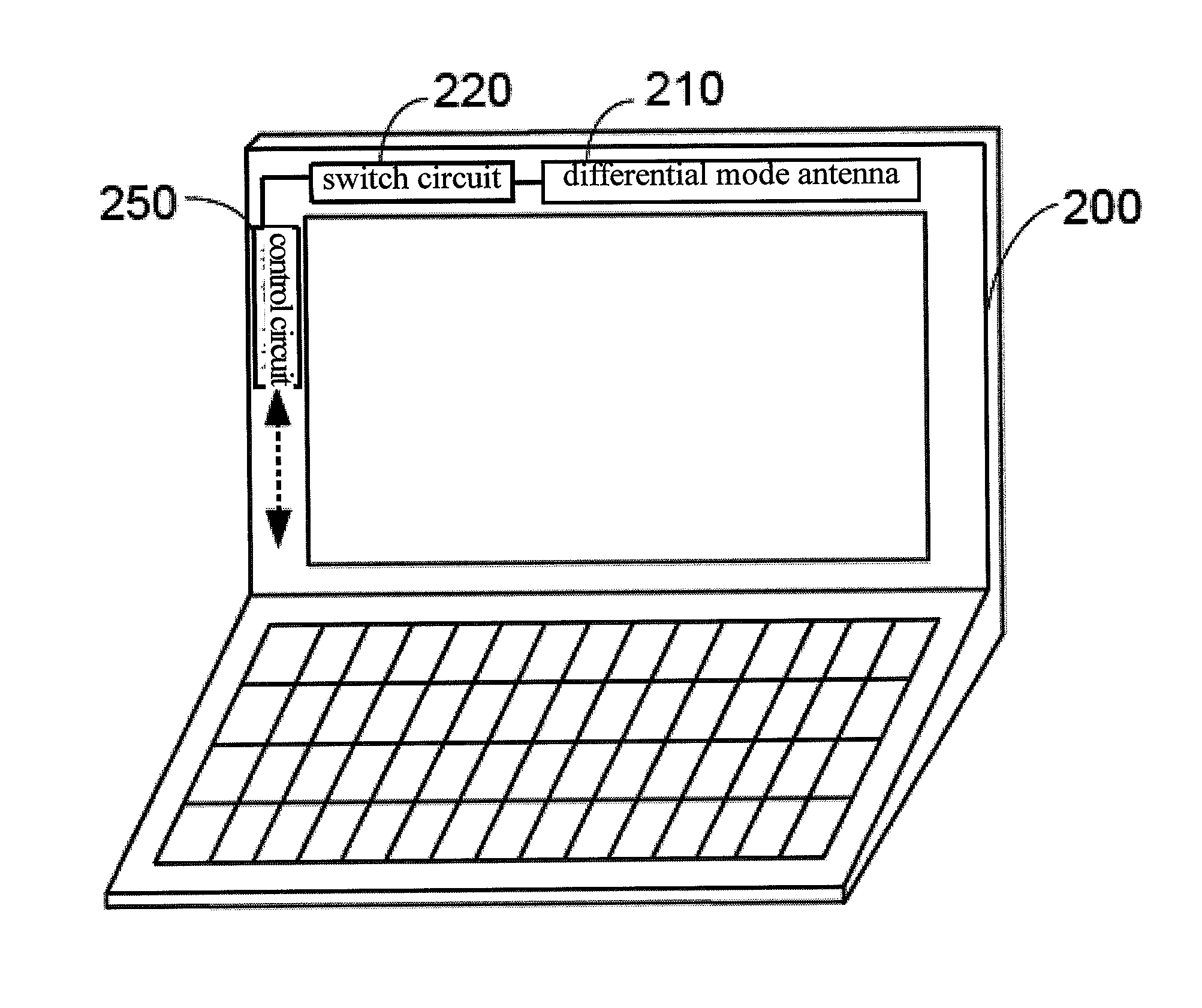
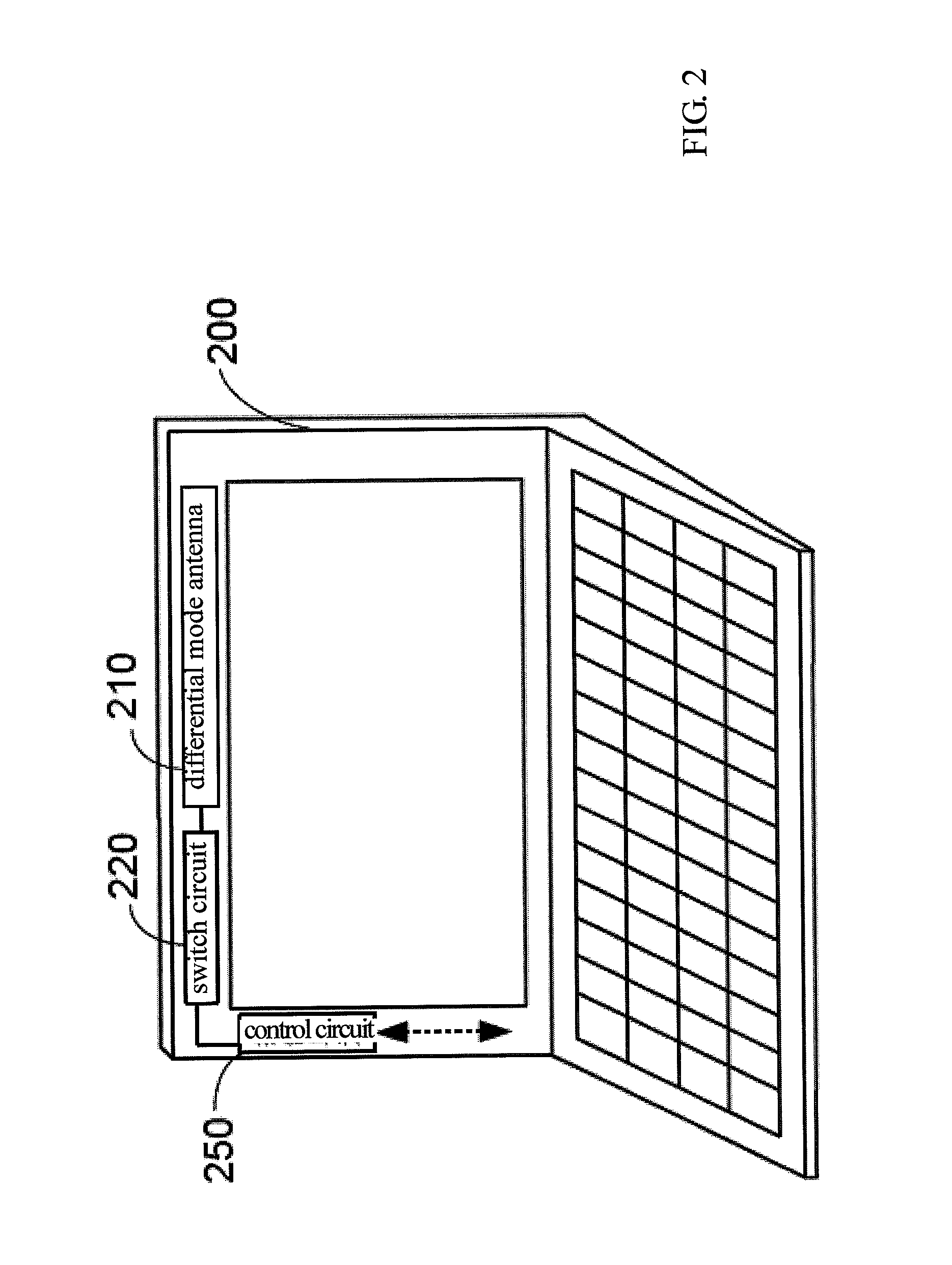
[0029]FIG. 3 is a block diagram showing a digital TV receiver in the invention. The differential antenna 210 uses a dipole antenna. Except for the dipole antenna, a loop antenna may also be used as the differential antenna 210. The differential RF signal outputted by the differential antenna 210 includes a positive signal S+ and a negative signal S−.
[0030]The switch circuit 220 includes a switch control circuit including multiple switches Sw1 to Sw4 and a plurality of matching circuits 221 to 228, and the control unit 250 may output a 2-bit selecting signal to the switches Sw1 to Sw4 of the switch circuit 220. The matching circuits 221 to 228 optimize the different bandwidths of the digital TV bandwidth, and improve the receiving efficiency of the bandwidth.
[0031]For example, when the selecting signal is “00”, the first switch Sw1 inputs the positive signal S+ to the 450-550 MHz matching circuit 221 which optimizes the signal with the 450 MHz to 550 MHz bandwidth in the positive sig...
second embodiment
[0037]FIG. 5 is a block diagram showing a digital TV receiver in the invention. The digital TV receiver includes a differential antenna 310, a front-end circuit 320, a switch circuit 330, and a control unit 350. The front-end circuit 320 is a differential LNA 322.
[0038]According to the second embodiment of the invention, the differential antenna 310 receives the broadcasting signal and outputs the differential RF signal which includes a positive signal S+ and a negative signal S−. The differential LNA 322 receives the differential RF signal and converts it to an amplified differential RF signal which includes an amplified positive signal Si+ and an amplified negative signal Si−.
[0039]The switch circuit 330 includes the switch control circuit including multiple switches Sw1 to Sw4 and a plurality of the matching circuits 331 to 338. The control unit 350 outputs a 2-bit selecting signal to the switches Sw1 to Sw4 of the switch circuit 330. The matching circuits 331 to 338 optimize the...
third embodiment
[0045]FIG. 6 is a block diagram showing a digital TV receiver in the invention. The digital TV receiver includes a differential antenna 410, a front-end circuit 420, a switch circuit 430, and a DVB module 450. The differential antenna 410 receives the broadcasting signal and converts it to the differential RF signal which includes a positive signal S+ and a negative signal S−.
[0046]The front-end circuit 420 receives the differential RF signal and converts it to a single ended signal. The front-end circuit 420 further includes a differential LNA 422 and a balun 424. The differential LNA 422 receives and amplifies the differential RF signal. Afterwards, the balun 424 converts the amplified differential RF signal to the single ended signal S.
[0047]The switch circuit 430 includes the switch control circuit including multiple switches Sw1 to Sw2 and a plurality of the matching circuits 432 to 435, and the DVB module 450 may output the 2-bit selecting signal to the switches Sw1 to Sw2 of ...
PUM
 Abstract
Description
Claims
Application Information
 - R&D
- Intellectual Property
- Life Sciences
- Materials
- Tech Scout
- Unparalleled Data Quality
- Higher Quality Content
- 60% Fewer Hallucinations
Browse by: Latest US Patents, China's latest patents, Technical Efficacy Thesaurus, Application Domain, Technology Topic, Popular Technical Reports.
© 2025 PatSnap. All rights reserved.Legal|Privacy policy|Modern Slavery Act Transparency Statement|Sitemap|About US| Contact US: help@patsnap.com


