Power supply device and method for detecting non-contact state of load connected to power supply device

a technology of power supply device and load, which is applied in the direction of electric devices, constant-current supply dc circuits, instruments, etc., can solve the problems of complex connector construction and the inability to distinguish between the connection state and the non-contact state of the load

Active Publication Date: 2011-09-01
SANYO ELECTRIC CO LTD
View PDF10 Cites 49 Cited by
  • Summary
  • Abstract
  • Description
  • Claims
  • Application Information

AI Technical Summary

Benefits of technology

[0009]To achieve the above object, a power supply device according to a first aspect of the present invention includes a battery, a positive terminal contactor, a negative terminal contactor, and a control portion. The battery includes rechargeable battery cells and supplies electric power to a load. The positive terminal contactor is serially connected to the positive side of the battery. The negative terminal contactor is serially connected to the negative side of the battery. The control portion determines whether the load connected to the output sides of the positive terminal contactor and the negative terminal contactor is in a connected state or a non-contact state. The control portion includes a voltage detecting circuit, and a determination circuit. The voltage detecting circuit detects the capacitor voltage of a capacitor that is connected to the output sides of the positive terminal contactor and the negative terminal contactor. The determination circuit compares the capacitor voltage detected by the voltage detecting circuit with a predetermined voltage, and determines the connected state of the load. According to this construction, when the power supply device is connected to a load, without using specially-designed circuits such as a connector including a connection detecting plug, the determination circuit compares the capacitor voltage detected by the voltage detecting circuit with a predetermined voltage, and can determine the connected state of the load. Therefore, this power supply device has an advantage that a load can be directly connected to the power supply device.
[0010]In a power supply device according to a second aspect of the present invention, the control portion includes a contactor controlling circuit that controls opening / closing of the negative terminal contactor. The voltage detecting circuit detects the capacitor voltage with the negative terminal contactor being closed by the contactor controlling circuit. When the capacitor voltage is not smaller than the predetermined voltage the determination circuit determines that the load is in the connected state. According to this construction, since, when the capacitor voltage is detected with the negative terminal contactor being closed, if this capacitor voltage is detected, it can be determined that the capacitor stores electric charge, in other words, that the power supply device is connected to the capacitor. Therefore, it is possible to easily determine the connected state.

Problems solved by technology

In the thus-constructed power supply device, since the connector necessarily includes the connection detecting plug for detecting the connection state of the load, there is a problem that the construction of the connector becomes complicated.
On the other hand, in the case of construction that the load is fastened without using the connector by fastening screws or the like, there is a problem that it is impossible to distinguish whether the connection state or the non-contact state of the load.

Method used


Image

  • Power supply device and method for detecting non-contact state of load connected to power supply device
  • Power supply device and method for detecting non-contact state of load connected to power supply device
  • Power supply device and method for detecting non-contact state of load connected to power supply device

Examples


Embodiment Construction

)

[0031]The following description will describe embodiments according to the present invention with reference to the drawings.

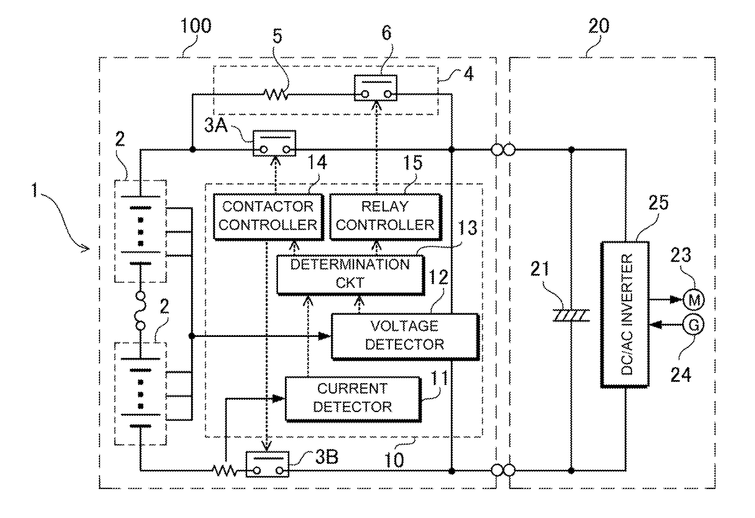
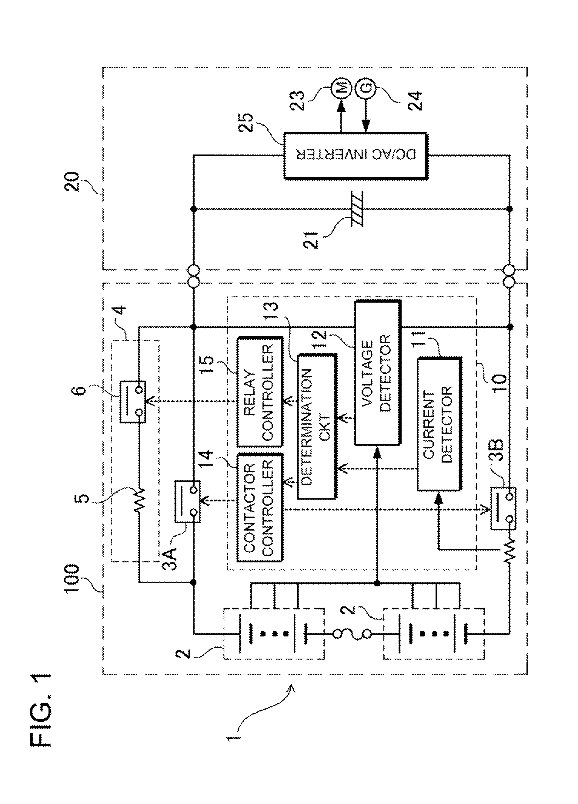
[0032]FIG. 1 shows a vehicle system that includes a power supply device according to an embodiment connected to a vehicle-side load. The illustrated vehicle power supply device is installed a hybrid car, electric vehicle or fuel cell electric vehicle, and drives an electric motor 23 connected as load for running the vehicle. This vehicle power supply device 100 includes a driving battery 1 including a plurality of battery units 2 that are connected to each other in series, a positive terminal contactor 3A that is serially connected to the positive side of the driving battery 1 and supplies electric power to the vehicle-side load 20, a negative terminal contactor 3B that is serially connected to the negative side of the driving battery, a precharge circuit 4 that is connected in parallel to the positive terminal contactor 3A, and a control portion 10 that detec...


PUM


Abstract

A power supply device includes a battery 1, positive and negative-side contactors 3A and 3B, and a controller 10. The battery 1 supplies power to a load 20. The positive-side contactor 3A is serially connected to the positive side of the battery 1. The negative-side contactor 3B is serially connected to the negative side of the battery 1. The controller 10 determines whether the load 20 connected to the output sides of the positive-side contactor 3A and the negative-side contactor 3B is in a connected or non-contact state. The controller 10 includes a voltage detecting circuit 12 that detects the capacitor voltage of a capacitor 21 connected to the output sides of the positive-side contactor 3A and the negative-side contactor 3B, and a determination circuit 13 that compares the detected voltage with a predetermined voltage and determines the connected state of the load 20.

Description

BACKGROUND OF THE INVENTION[0001]1. Field of the Invention[0002]The present invention relates to a power supply device that is installed on a hybrid car, electric vehicle or fuel-cell vehicle and supplies electric power to a driving electric motor for running the vehicle, and a method for detecting the non-contact state of a load connected to a power supply device.[0003]2. Description of the Related Art[0004]A power supply device has been developed that includes a contactor on the output side through which a load is connected to the power supply device (see Japanese Patent Laid-Open Publication No. 2006-216516).[0005]The load connected to this power supply device is a DC / AC inverter. A large-capacitance capacitor is connected in parallel to the input side of the DC / AC inverter. A driving electric motor and an electric generator are connected to the output side of the DC / AC inverter. In the case where this power supply device is connected to the load, when an ignition switch as main ...

Claims


Application Information

Patent Timeline
IPC IPC(8): G01N27/416
CPCB60L3/04B60L11/1803B60L11/1816B60L11/1861Y02T90/14Y02T10/7005Y02T10/7044Y02T10/705B60L11/1877B60L50/51B60L50/66B60L53/14Y02T10/70Y02T10/7072
Inventor YUGOU, MASAKIYAMAUCHI, YUTAKA
Owner SANYO ELECTRIC CO LTD
Why Eureka
Try Eureka