Direct oxidation fuel cell

a fuel cell and direct oxidation technology, applied in the direction of fuel cells, fuel cells, solid electrolyte fuel cells, etc., can solve the problems of reducing power generation efficiency, lowering voltage, and dmfcs currently have to be solved, so as to achieve better understanding, reduce the effect of fuel crossover and better understanding

Inactive Publication Date: 2011-08-25
PANASONIC CORP
View PDF5 Cites 6 Cited by
  • Summary
  • Abstract
  • Description
  • Claims
  • Application Information

AI Technical Summary

Benefits of technology

[0027]According to the invention, by making the loading density of the anode catalyst particles in the anode catalyst layer upstream of the fuel flow channel higher than the loading density of the anode catalyst particles downstream, more fuel can be consumed upstream of the fuel flow channel in the anode catalyst layer than downstream. As a result, upstream of the fuel flow channel in the anode catalyst layer, the fuel concentration at the interface between the anode catalyst layer and the electrolyte membrane can be lowered, compared with conventional techniques. Hence, fuel crossover can be reduced. That is, the difference in the fuel concentration between a first interface between the anode catalyst layer and the anode diffusion layer and a second interface between the anode catalyst layer and the electrolyte membrane can be increased upstream of the fuel flow channel in the anode catalyst layer, while it can be decreased downstream of the fuel flow channel in the anode catalyst layer.
[0028]While the novel features of the invention are set forth particularly in the appended claims, the invention, both as to organization and content, will be better understood and appreciated, along with other objects and features thereof, from the following detailed description taken in conjunction with the drawings.

Problems solved by technology

Direct oxidation fuel cells such as DMFCs currently have a technical problem to be solved.
Hence, fuel crossover results in lowered voltage, decreased power generation efficiency, etc.
Methanol has high affinity with water, and it is thus not possible to sufficiently prevent methanol from passing through the electrolyte membrane together with water.

Method used


Image

  • Direct oxidation fuel cell
  • Direct oxidation fuel cell
  • Direct oxidation fuel cell

Examples


example 1

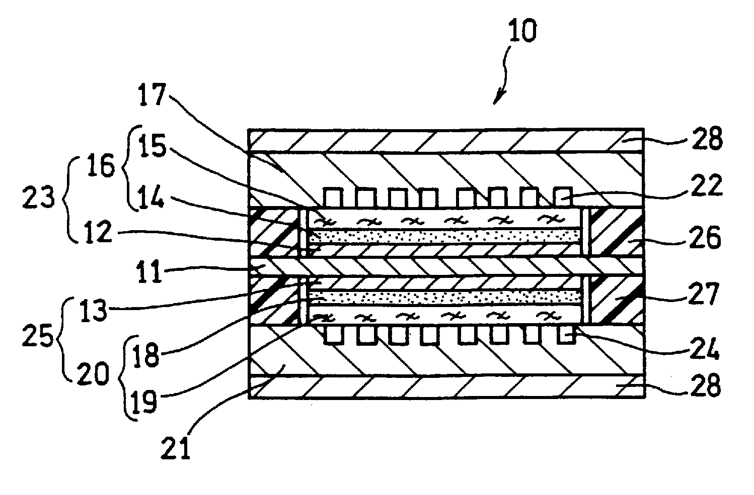
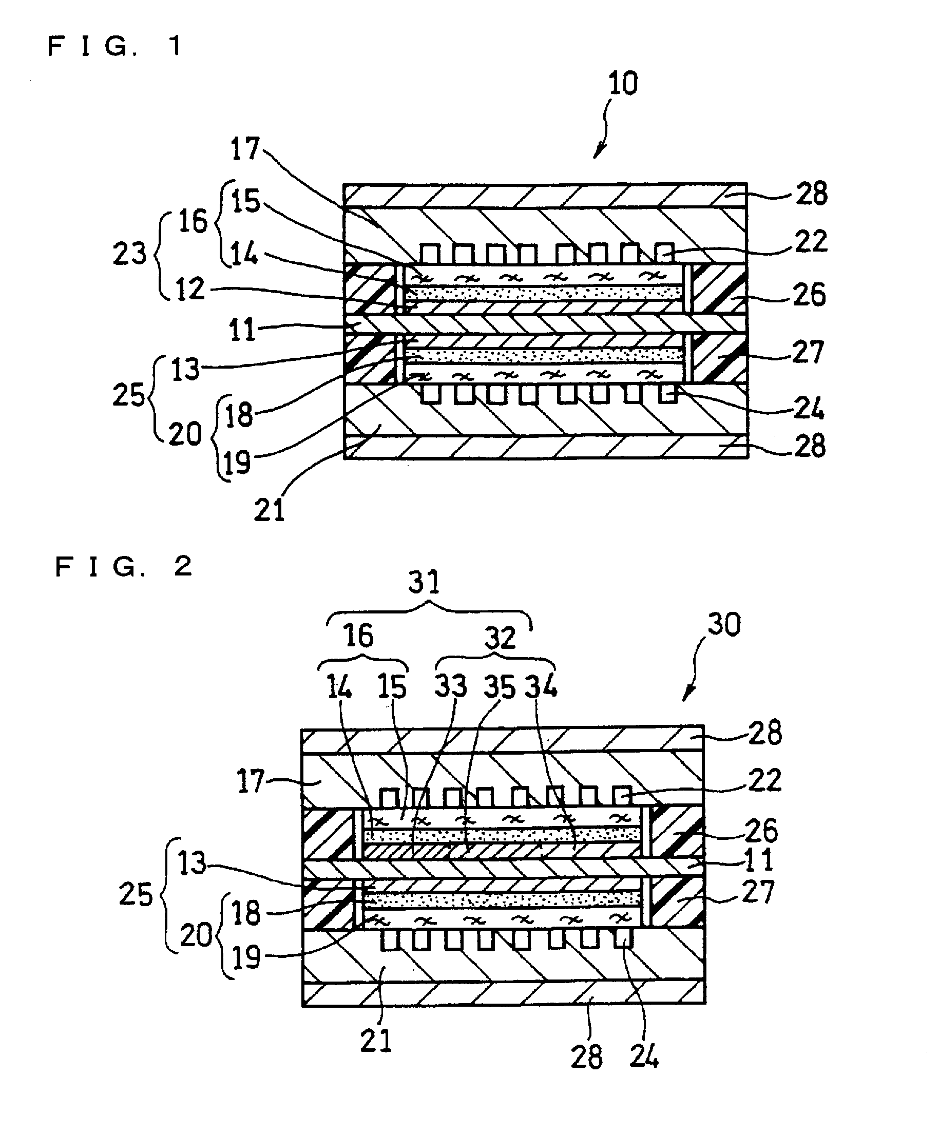
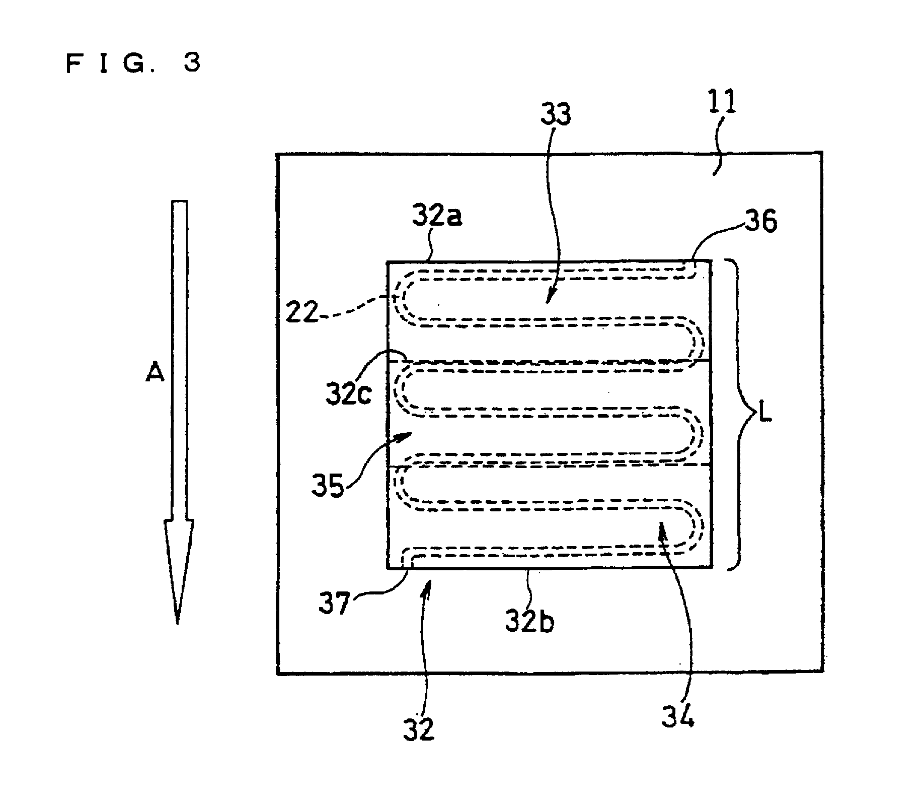
[0129]In this example, a fuel cell as illustrated in FIG. 2 and FIG. 3 was produced.

[0130]A supported anode catalyst comprising anode catalyst particles supported on a support was prepared. A platinum (Pt)-ruthenium (Ru) alloy (atomic ratio 1:1) (average particle size: 5 nm) was used as the anode catalyst particles. Conductive carbon particles with an average primary particle size of 30 nm were used as the support. The ratio of the mass of the Pt—Ru alloy to the total mass of the Pt—Ru alloy and the conductive carbon particles was set to 80 mass %.

[0131]A supported cathode catalyst comprising cathode catalyst particles supported on a support was prepared. Platinum (average particle size: 3 nm) was used as the cathode catalyst particles. Conductive carbon particles with an average primary particle size of 30 nm were used as the support. The ratio of the mass of platinum to the total mass of platinum and the conductive carbon particles was set to 80 mass %.

[0132]A 50 μm-thick fluorine...

example 2

[0157]In this example, the loading densities of the anode catalyst particles in the respective regions of the anode catalyst layer were changed by adding a pore-forming agent to the anode-catalyst-layer forming ink and changing the amount of the pore-forming agent. In this example, lithium carbonate was used as the pore-forming agent.

[0158]Specifically, in the same manner as in Example 1, the anode catalyst layer was composed of three regions of a first region, a third region, and a second region. The size of each region was set to 20 mm×60 mm.

[0159]A first ink for forming the first region was prepared by mixing 2 g of lithium carbonate per 80 g of the anode-catalyst-layer forming ink used in Example 1 and dispersing it.

[0160]A third ink for forming the third region was prepared by mixing 5 g of lithium carbonate per 80 g of the anode-catalyst-layer forming ink used in Example 1 and dispersing it.

[0161]A second ink for forming the second region was prepared by mixing 10 g of lithium...

example 3

[0169]In this example, the loading density of the anode catalyst particles was changed by changing the support ratio of the anode catalyst particles supported on the support. The support ratio represents the mass ratio of the anode catalyst particles to the total mass of the anode catalyst particles (Pt—Ru alloy) and the support.

[0170]In this example, a Pt—Ru alloy (atomic ratio 1:1) was used as the anode catalyst particles in the same manner as in Example 1. Conductive carbon particles with an average primary particle size of 30 nm were used as the support.

[0171]Also, the anode catalyst layer was composed of three regions of a first region, a third region, and a second region. The size of each region was set to 20 mm×60 mm.

[0172]The support ratio of the anode catalyst particles of the supported anode catalyst (first supported catalyst) contained in the first region was set to 80%. The first region was produced in the same manner as the preparation method of the first region of Exam...


PUM

PropertyMeasurementUnit
loading densityaaaaaaaaaa
particle sizeaaaaaaaaaa

Abstract

The invention relates to a direct oxidation fuel cell. The invention intends to provide a fuel cell having good fuel utilization efficiency and good power generation performance such as voltage produced and power generation efficiency by suppressing the phenomenon of the fuel supplied from the fuel flow channel passing through the electrolyte membrane and being oxidized at the cathode. The direct oxidation fuel cell of the invention includes at least one unit cell which includes: a membrane electrode assembly including an anode, a cathode, and an electrolyte membrane interposed therebetween; an anode-side separator, and a cathode-side separator. The anode-side separator has a fuel flow channel for supplying a fuel to the anode. The anode has an anode catalyst layer including anode catalyst particles and a polymer electrolyte. The loading density of the anode catalyst particles in the anode catalyst layer is higher upstream than downstream of the fuel flow channel.

Description

TECHNICAL FIELD[0001]This invention relates to direct oxidation fuel cells such as direct methanol fuel cells, and more particularly to an improvement in the cell structure of a direct oxidation fuel cell.BACKGROUND ART[0002]Fuel cells are classified into, for example, solid polymer fuel cells, phosphoric acid fuel cells, alkaline fuel cells, molten carbonate fuel cells, and solid oxide fuel cells, according to the kind of the electrolyte used. Among them, solid polymer fuel cells (PEFCs), which operate at low temperatures and have high output densities, are becoming commercially available as the power source for automobiles, home cogeneration systems, etc.[0003]Recently, the use of fuel cells as the power source for portable small electronic devices, such as notebook personal computers, cellular phones, and personal digital assistants (PDAs), has been examined. Since fuel cells can generate power continuously if refueled, the use of fuel cells in place of secondary batteries, which...

Claims


Application Information

Patent Timeline
Patent Type & Authority Applications(United States)
IPC IPC(8): H01M8/10H01M4/86
CPCH01M4/8642Y02E60/50H01M8/1009H01M4/92
Inventor AKIYAMA, TAKASHI
Owner PANASONIC CORP
Why Eureka
Try Eureka