
Frequency modulation type wirelss power supply and charger system

a technology of wireless power supply and charger system, which is applied in the direction of reradiation, instruments, transportation and packaging, etc., can solve the problems of not being able to charge the rechargeable battery of the mobile electronic product, not being able to find and pick up the correct battery charger, and not being able to meet the needs of users, so as to avoid short circuit or any possible damage, and double safety protection

Active Publication Date: 2011-08-18
FU TONG TECH
View PDF2 Cites 328 Cited by
  • Summary
  • Abstract
  • Description
  • Claims
  • Application Information

AI Technical Summary

Benefits of technology

[0013]The present invention has been accomplished under the circumstances in view. It is one object of the present invention to provide a frequency modulation type wireless power supply and charger system, which minimizes power transmission loss and the load of the internal components, thereby saving power consumption.
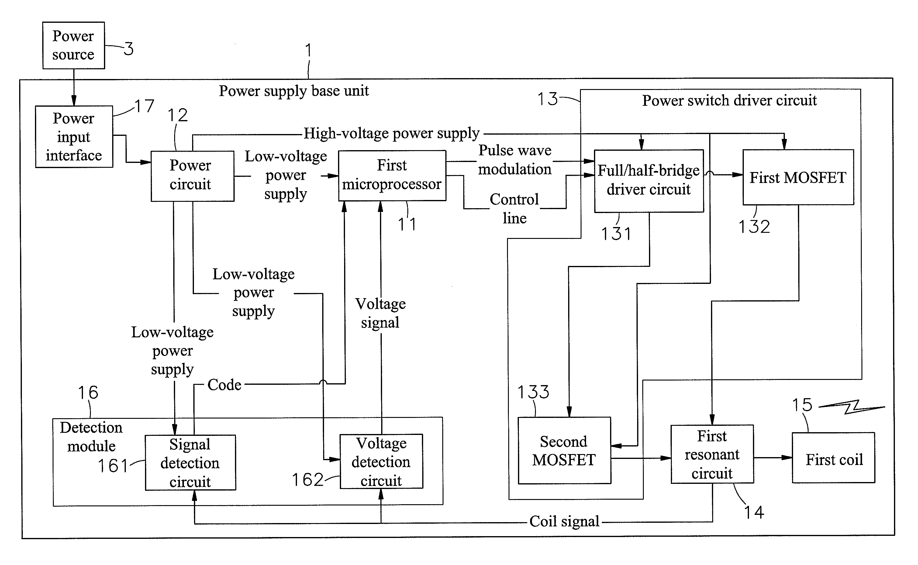
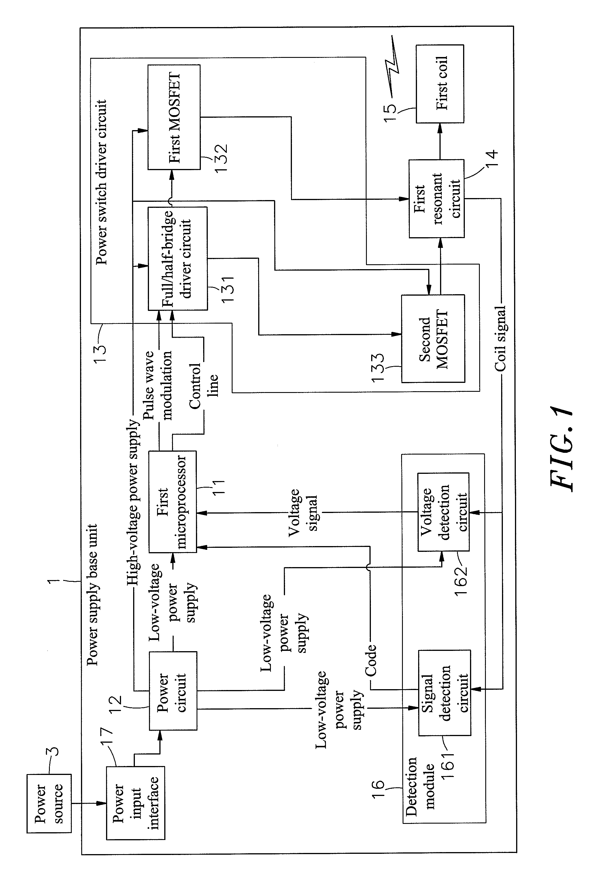
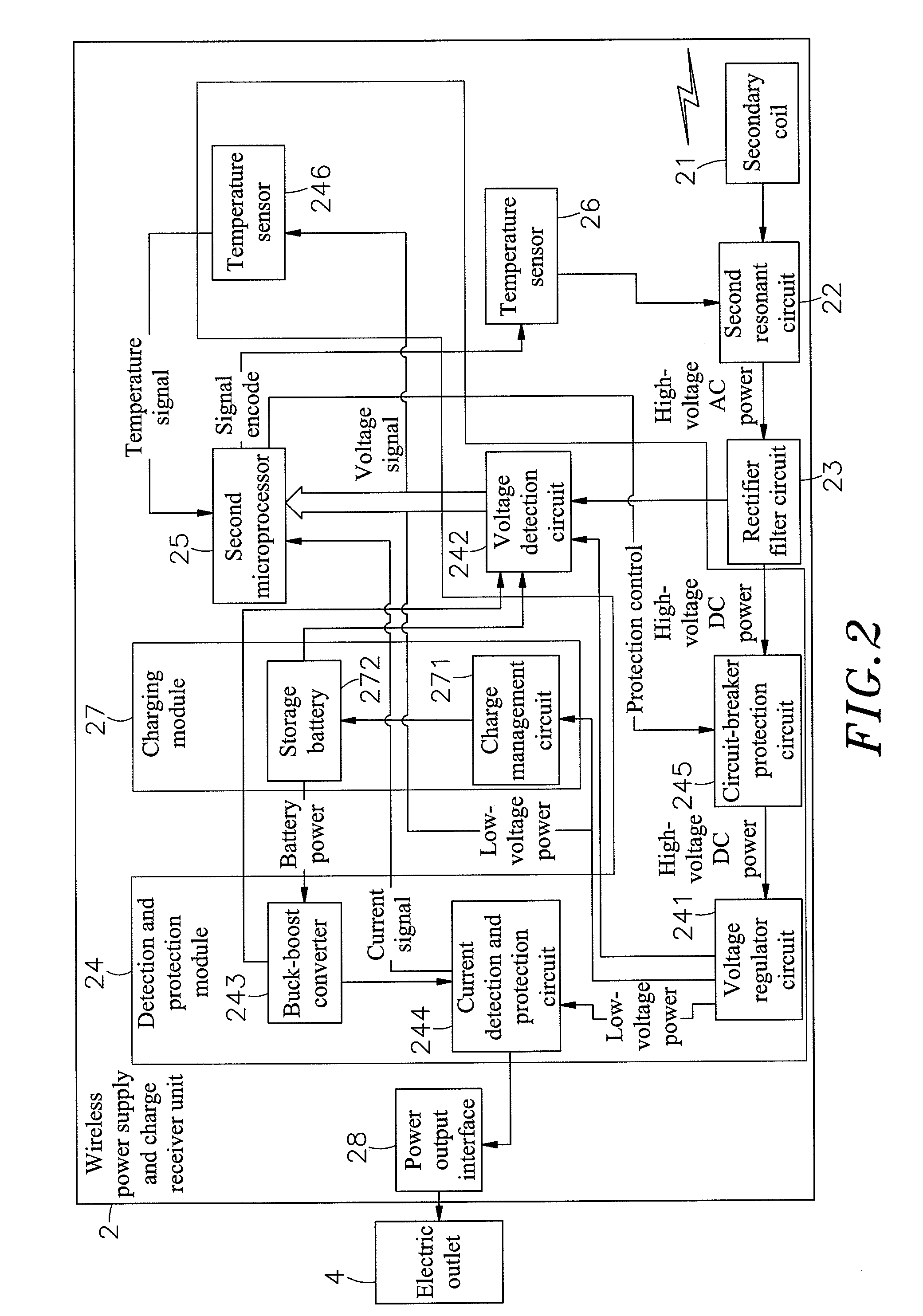
[0014]To achieve this and other objects of the present invention, a frequency modulation type wireless power supply and charger system comprises a power supply base unit, and a wireless power supply and charge receiver unit adapted for receiving electrical power from the power supply base unit wirelessly for charging an external electronic device being connected thereto. The power supply base unit consists of a first microprocessor, a power circuit, a power switch driver circuit, a first resonant circuit, a first coil, a detection module and a power input interface. The wireless power supply and charge receiver unit consists of a secondary coil, a second resonant circuit, a rectifier filter circuit, a detection and protection module, a second microprocessor, a temperature sensor, a charging module and a power output interface. The detection and protection module of the wireless power supply and charge receiver unit detects the supply of the electrical power received from the power supply base unit so that the second microprocessor sends a feedback signal to the power supply base unit through the signal generator circuit and the second resonant circuit for enabling the power supply base unit to control the power switch driver circuit to regulate its output power automatically, thereby minimizing power transmission loss and the load of the internal components of the wireless power supply and charge receiver unit.
[0015]Further, the power switch driver circuit of the power supply base unit comprises a full / half-bridge driver circuit, a first MOSFET (metal oxide semiconductor field effect transistor) array and a second MOSFET (metal oxide semiconductor field effect transistor) array. The first MOSFET (metal oxide semiconductor field effect transistor) array and the second MOSFET (metal oxide semiconductor field effect transistor) array are connected in parallel to the full / half-bridge driver circuit. Thus, the full / half-bridge driver circuit can switch the output power rapidly under a continuous operation status. When does no work, the full / half-bridge driver circuit can cut off the first MOSFET (metal oxide semiconductor field effect transistor) array and the second MOSFET (metal oxide semiconductor field effect transistor) array, avoiding power leakage and minimizing static power consumption.
[0016]Further, the first coil and the second coil are respectively made by: twisting multiple enameled wires together and bonding the twisted enameled wires with an insulative adhesive to form a wire material and then using a mold to wind the wire material into a flat, rectangular configuration. Thus, the first coil and the second coil have low impedance and high inductance characteristics when used for high frequency application, reducing the amount of heat and improving the transmission efficiency and performance.
[0017]Further, the resonant capacitor of the second resonant circuit of the wireless power supply and charge receiver unit is connected in series to the second coil, assuring zero power consumption during zero load resonance and high power obtaining during a high load.
[0018]Further, the circuit-breaker protection circuit of the detection and protection module of the wireless power supply and charge receiver unit is electrically connected between the voltage regulator circuit and the rectifier filter circuit. The current detection and protection circuit of the detection and protection module is electrically connected to the voltage regulator circuit and the buck-boost converter. Further, the current detection and protection circuit uses a reset fuse for overcurrent protection. In case of an overcurrent, electrical power is automatically cut off from the circuit-breaker protection circuit, and the reset fuse of the current detection and protection circuit opens the circuit for protection. Therefore the invention achieves a double safety protection, avoiding a short circuit or any possible damage.

Problems solved by technology

However, it is not economic to purchase one respective battery charger when buying a new mobile electronic product.
Further, it takes much time to find and pick up the correct battery charger from the storage group of battery chargers.
When one goes out to a place there is no any electric outlet available, the user will be unable to charge the rechargeable battery of his(her) mobile electronic product.
1. The power transmitting side of these conventional electromagnetic induction type power transmission products is formed of a coil and a resonant circuit and does not allow adjustment of the output power when electrically connected. When the power requirement of the electronic product at the receiving side is changed, the output power of the power transmitting side cannot be regulated to match the demand, causing power insufficiency or power waste.
2. The resonant capacitor and the receiving coil at the receiving side are connected in parallel. Thus, the resonant capacitor and the receiving coil keep consuming electrical power when receives no load, wasting the energy.
3. The coils are prepared from a single-core enameled wire. During high frequency application, the coils produce much heat, lowering the transmission efficiency and performance.
4. These conventional electromagnetic induction type power transmission products do not provide any safety circuit means at the receiving side, and the electronic device under charging may be damaged in case of a short circuit or overcurrent.

Method used


Image

  • Frequency modulation type wirelss power supply and charger system
  • Frequency modulation type wirelss power supply and charger system
  • Frequency modulation type wirelss power supply and charger system

Examples


Embodiment Construction

[0025]Referring to FIG. 1 and FIG. 2, a frequency modulation type wireless power supply and charger system in accordance with the present invention is shown comprising a power supply base unit 1 and a wireless power supply and charge receiver unit 2.

[0026]The power supply base unit 1 comprises a first microprocessor 11, a power circuit 12, a power switch driver circuit 13, a first resonant circuit 14, a first coil 15 and a detection module 16. The power circuit 12 is electrically connected to the first microprocessor 11 and electrically connected to an external power source 3 and adapted for providing a low voltage power supply to the first microprocessor 11. The power switch driver circuit 13 is electrically connected to the first microprocessor 11 and the power circuit 12, and adapted for providing a high voltage power supply to the first microprocessor 11. Further, the power switch driver circuit 13 comprises a full / half-bridge driver circuit 131, a first MOSFET (metal oxide semi...


PUM


Abstract

A frequency modulation type wireless power supply and charger system includes a power supply base unit consisting of a first microprocessor, a power circuit, a power switch driver circuit, a first resonant circuit, a first coil, a detection module and a power input interface, and a wireless power supply and charge receiver unit consisting of a secondary coil, a second resonant circuit, a rectifier filter circuit, a detection and protection module, a second microprocessor, a temperature sensor, a charging module and a power output interface and adapted for receiving electrical power from the power supply base unit wirelessly for charging an external electronic device. The detection and protection module of the wireless power supply and charge receiver unit detects the supply of the electrical power, and the second microprocessor sends a feedback signal to the power supply base unit through the signal generator circuit and the second resonant circuit subject to the detection of the detection and protection module for enabling the power supply base unit to control the power switch driver circuit to regulate its output power automatically, thereby minimizing power transmission loss and the load of the internal components of the wireless power supply and charge receiver unit.

Description

[0001]This application claims the priority benefit of Taiwan patent application number 099203171 file on Feb. 12, 2010.BACKGROUND OF THE INVENTION[0002]1. Field of the Invention[0003]The present invention relates to wireless electrical power supplying techniques and more particularly, to a frequency modulation type wireless power supply and charger system, which comprises a power supply base unit connected to an external power source, and a wireless power supply and charge receiver unit adapted for receiving electrical power from said power supply base unit wirelessly for charging an external electronic device being connected thereto, wherein the detection and protection module of the wireless power supply and charge receiver unit detects the electrical power provided by the power supply base unit and sends a feedback signal to the power supply base unit for causing the power supply base unit to regulate its output power, thereby saving power consumption and minimizing the load.[000...

Claims


Application Information

Patent Timeline
Patent Type & Authority Applications(United States)
IPC IPC(8): H02J7/00
CPCH02J7/025H02M3/3376Y02B70/1491Y02B70/1433H02M2001/0048H02J50/12H02J50/20H02J50/80H02J7/00034Y02B70/10H02M1/0048H02J50/70
Inventor TSAI, MING-CHIUCHAN, CHI-CHE
Owner FU TONG TECH
Learn More