
Liquid crystal display device

a liquid crystal display and display panel technology, applied in the direction of electrical apparatus casings/cabinets/drawers, instruments, computing, etc., can solve the problems of display panel damage, display panel damage, image defects, etc., and achieve the effect of preventing short circui

Inactive Publication Date: 2011-08-04
SAMSUNG DISPLAY CO LTD
View PDF5 Cites 24 Cited by
  • Summary
  • Abstract
  • Description
  • Claims
  • Application Information

AI Technical Summary

Benefits of technology

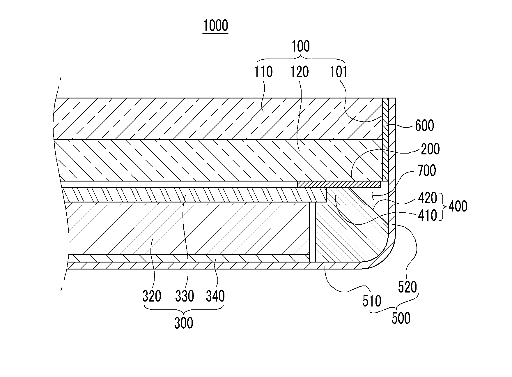
[0009]The described technology has been made in an effort to provide a slim liquid crystal display (LCD), wherein a short circuit is prevented between a display panel and a housing.
[0010]Aspects of the present invention provide a slim liquid crystal display (LCD) that can prevent damage to a display panel by minimizing impacts between a display panel and a housing.
[0017]According to an exemplary embodiment, since a resin unit is provided between a display panel and a housing, a slim liquid crystal display (LCD) that prevents a short circuit between wiring of a display panel and a housing, is provided.
[0018]According to various embodiments, a slim liquid crystal display (LCD) is provided that prevents a display panel from being broken, by including a resin unit between the display panel and a housing, to minimize the effect of impacts to the housing.

Problems solved by technology

However, since the edges of the display panel directly face the housing, when the housing is formed with a conductive material such as metal, a short circuit occurs between the display panel and the housing, which generates image defects.
Also, since the edges of the display panel face the housing, when an impact is applied to the housing, one of the edges of the display panel impacts the housing.
As a result, in the display panel may be broken.
Further, the display panel is affixed to the backlight unit using an adhesive, such as an adhesive tape, and when the adhesive ingredients of the tape are deteriorated, the display panel may become separated from the backlight unit.

Method used


Image

  • Liquid crystal display device
  • Liquid crystal display device
  • Liquid crystal display device

Examples


Embodiment Construction

[0025]Reference will now be made in detail to the exemplary embodiments of the present invention, examples of which are illustrated in the accompanying drawings, wherein like reference numerals refer to the like elements throughout. The exemplary embodiments are described below, in order to explain the aspects of present invention, by referring to the figures. As those skilled in the art would realize, the described embodiments may be modified in various different ways, all without departing from the spirit or scope of the present invention.

[0026]In the drawings, the thickness of layers, films, panels, regions, etc., may be exaggerated for clarity. It will be understood that when an element such as a layer, film, region, or substrate is referred to as being disposed “on” another element, it can be disposed directly on the other element, or may be indirectly disposed on the other element, with intervening elements disposed therebetween.

[0027]In addition, unless explicitly described t...


PUM


Abstract

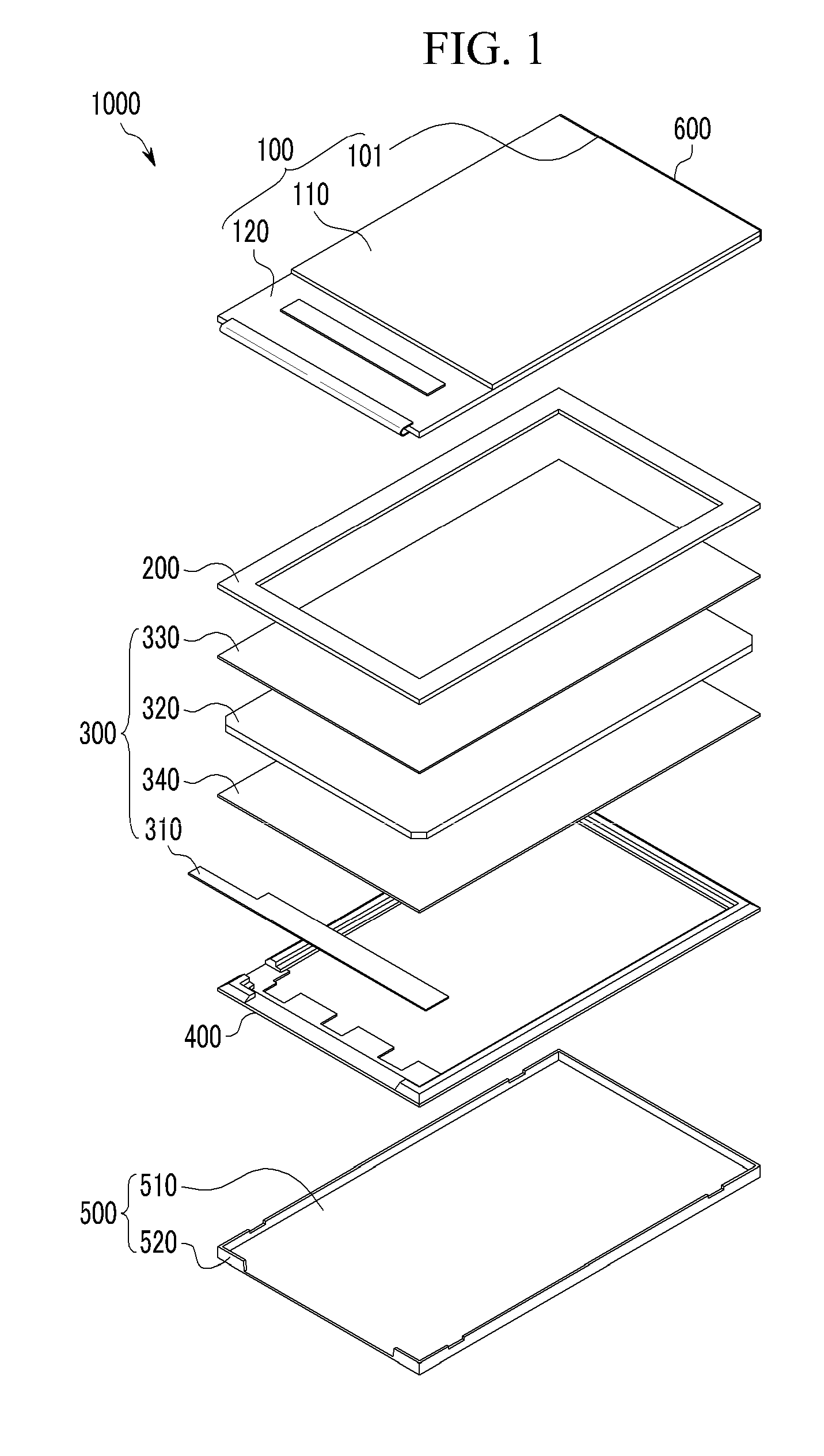
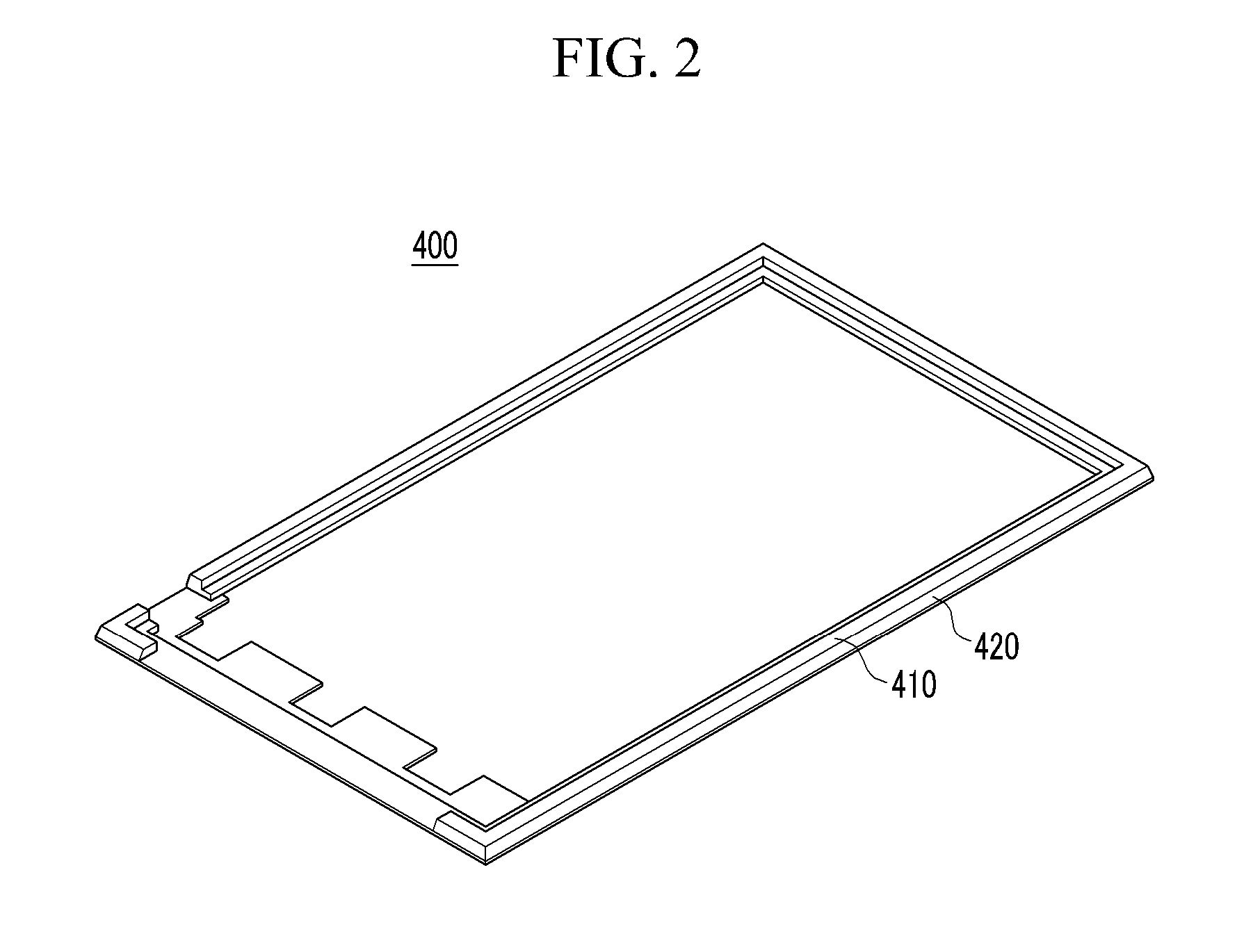
A liquid crystal display (LCD) including: a display panel; a backlight unit to radiate light to the display panel; a mold frame surrounding the backlight unit and supporting the display panel; a housing to receive the display panel, backlight unit, and mold frame; and a resin unit provided between the display panel and the housing. A receiving groove is formed below the resin unit, by sloped surfaces of the mold frame and side walls of the housing.

Description

RELATED APPLICATION[0001]This application claims the benefit of Korean Patent Application No. 10-2010-0009588, filed on Feb. 2, 2010, in the Korean Intellectual Property Office, the disclosure of which is incorporated herein by reference.BACKGROUND[0002]1. Field[0003]The described technology relates generally to a slim liquid crystal display (LCD).[0004]2. Description of the Related Art[0005]A liquid crystal display (LCD) is a display device that displays images using a liquid crystal layer that operates as a shutter. A conventional liquid crystal display (LCD) includes a display panel including a liquid crystal layer, a backlight unit to radiate light to the display panel, and a housing to receive the display panel and the backlight unit.[0006]Recently, a slim liquid crystal display (LCD), of which edges of a display panel face a housing, has been developed, so as to reduce an area between an image display area of the display panel and the housing. However, since the edges of the d...

Claims


Application Information

Patent Timeline
IPC IPC(8): G02F1/1333
CPCG02F1/1333G02F1/133308G02F2201/50G02F2202/28
Inventor KIM, JEUNG-SOOLEE, SANG-HEEHWANG, JEONG-HORO, SEUNG-MOCKBAE, KYU-HAN
Owner SAMSUNG DISPLAY CO LTD
Learn More