
Electric discharge machine and method of producing nozzle body using the same

a technology of electric discharge machine and nozzle body, which is applied in the direction of electric circuit, manufacturing tools, and vibration holders of electric devices, can solve the problems of insufficient first feedback control and long time for forming all holes in this situation, and achieve the effect of shortening the processing tim

Active Publication Date: 2011-08-04
DENSO CORP
View PDF17 Cites 9 Cited by
  • Summary
  • Abstract
  • Description
  • Claims
  • Application Information

AI Technical Summary

Benefits of technology

[0007]In view of the foregoing and other problems, it is a first object of the present invention to provide an electric discharge machine having plural electrodes so as to process plural holes in a work piece by a single processing operation, thereby the processing time is shortened.

Problems solved by technology

It takes a long time to form all the holes in this situation.
However, the first feedback control is not sufficiently accurate, because the electrode may still being controlled by the motor at a timing when the discharge state is detected.
Therefore, the second feedback control is necessary because the accuracy of the first feedback control is not enough.

Method used


Image

  • Electric discharge machine and method of producing nozzle body using the same
  • Electric discharge machine and method of producing nozzle body using the same
  • Electric discharge machine and method of producing nozzle body using the same

Examples


first embodiment

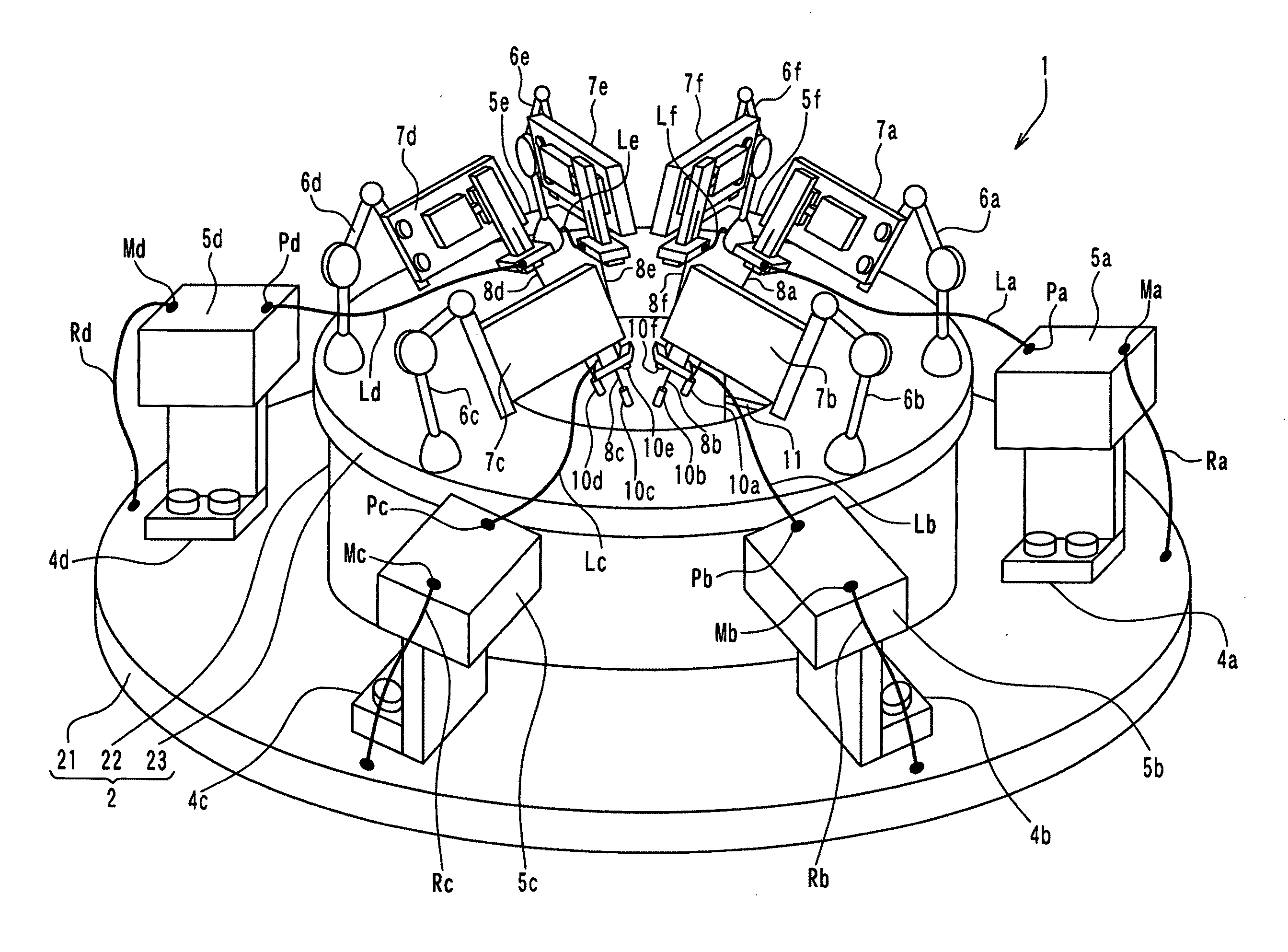
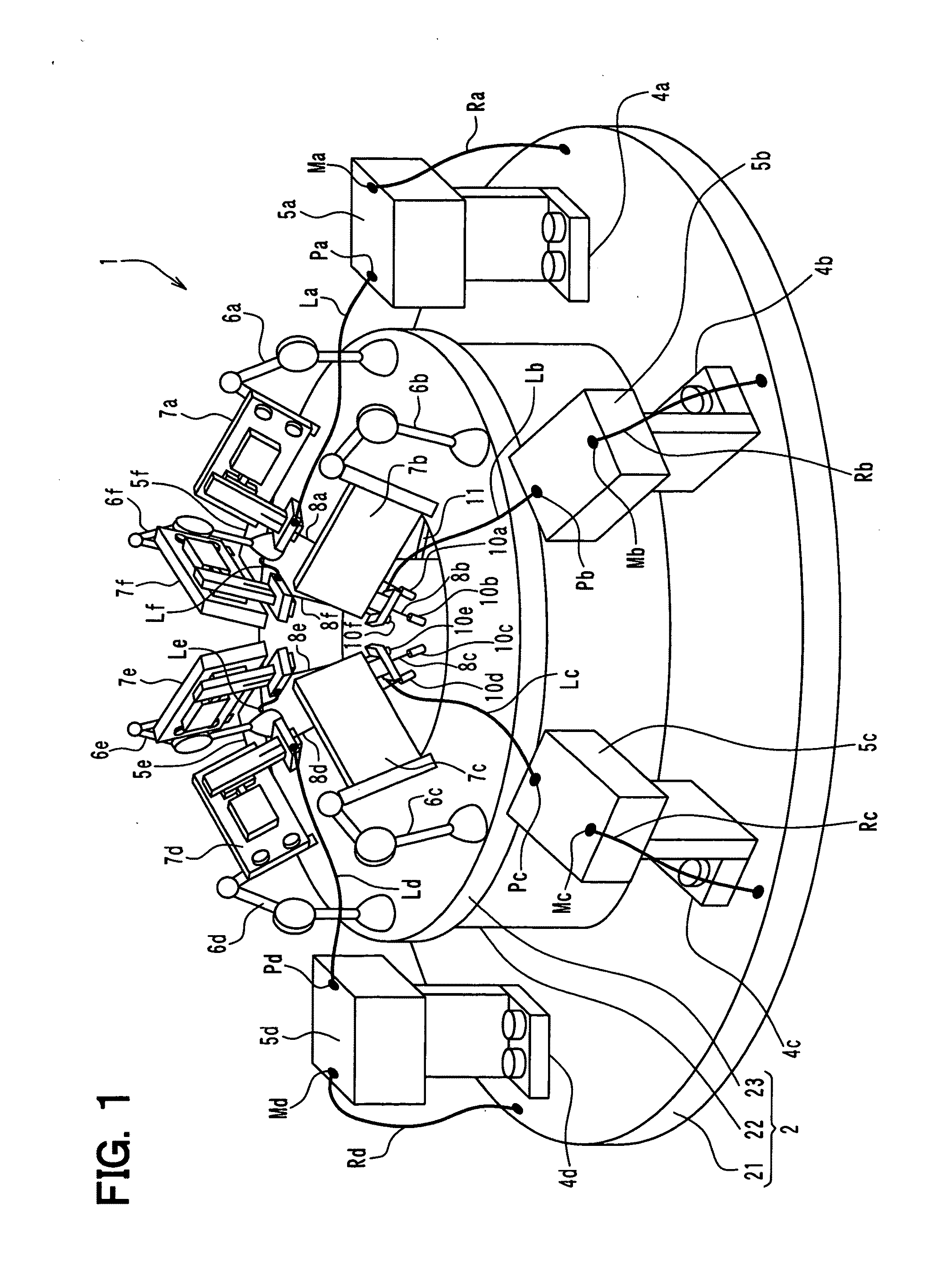
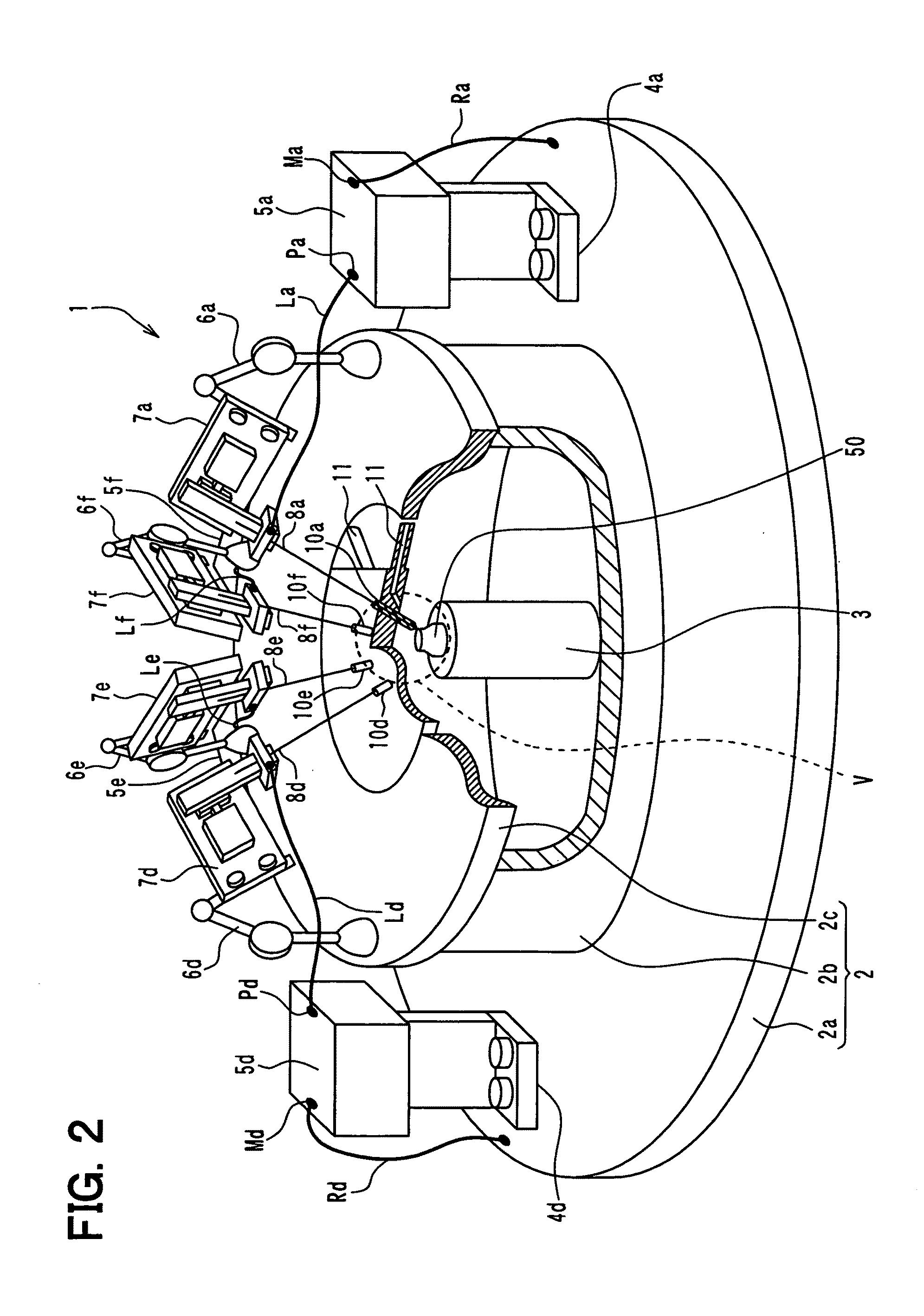
[0065]A first embodiment of the present invention will be described below. A construction of an electric discharge machine 1 according to the present embodiment is shown in FIGS. 1-6. FIG. 1 is a perspective view illustrating the electric discharge machine 1. FIG. 2 is a perspective view illustrating the electric discharge machine 1 of FIG. 1 in which a front part of it is removed. FIG. 3 is a plan view illustrating the electric discharge machine 1. FIG. 4 is a cross-sectional view taken along line IV-IV of FIG. 3. FIG. 5 is an enlarged view of a section V surrounded by a dashed line in FIG. 2. FIG. 6 is a block diagram illustrating a control construction of the electric discharge machine 1.

[0066]As shown in FIGS. 1-5, the electric discharge machine 1 includes a body 2, a work holder 3 located inside of the body 2, stays 4a-4f, discharge power supply units 5a-5f, fixed rods 6a-6f, discharge head units 7a-7f, power feeding lines La-Lf, Ra-Rf, electrodes 8a-8f, an electrode guide hold...

second embodiment

[0135]A second embodiment of the present invention will be described below. A construction of an electric discharge machine 201 according to the present embodiment is shown in FIG. 11. Discharge is generated by applying voltage between an electrode and a work piece, thereby the machine 201 processes the work piece by melting.

[0136]As shown in FIG. 11, the electric discharge machine 201 has a mechanism part 202, a discharge power source 203, a discharge state detector circuit 204, a motor amplifier 205, and a controlling circuit 206. The mechanism part 202 of the electric discharge machine 201 is a portion to perform a mechanical operation, and has an ultrasonic motor 221, an electrode holder 222, and an electrode 223, for example. A work piece 224 is arranged in the mechanism part 202.

[0137]The ultrasonic motor 221 is a motor to move the electrode holder 222 in a drive direction (specifically, up or down). The electrode holder 222 is a component to hold the electrode 223. The electr...


PUM

PropertyMeasurementUnit
diameteraaaaaaaaaa
heightaaaaaaaaaa
diameteraaaaaaaaaa

Abstract

An electric discharge machine to process a work piece includes a plurality of electrodes, and a plurality of discharge power supply units. The plurality of electrodes generate a plurality of discharges with the work piece, respectively. The plurality of discharge power supply units apply voltages for the plurality of electrodes, respectively and independently.

Description

CROSS REFERENCE TO RELATED APPLICATION[0001]This application is based on Japanese Patent Application No. 2009-258785 filed on Nov. 12, 2009 and Japanese Patent Application No. 2009-260801-filed on Nov. 16, 2009, the disclosures of which are incorporated herein by reference in their entirety.BACKGROUND[0002]The present invention relates to an electric discharge machine and a method of producing a nozzle body using the electric discharge machine.[0003]Discharge is generated by applying voltage between an electrode and a work piece, thereby a hole is formed in the work piece. JP-A-H9-85536 or JP-A-2001-259933 describes such a technology for forming plural holes in a work piece by a single processing operation. Specifically, plural electrodes are moved toward the work piece, and pulse voltages are periodically impressed to the electrodes, at the same time.[0004]However, in this case, discharge usually occurs between only one electrode and the work piece based on the timings of impressin...

Claims


Application Information

Patent Timeline
Patent Type & Authority Applications(United States)
IPC IPC(8): B23H1/02
CPCB23H1/02B23H1/028B23H9/14
Inventor ITOH, AKIRAINOBE, YASUJIADACHI, HIROSHIOOCHI, TAKESHIIKUTA, KAZUHISAKAMEYAMA, MICHIO
Owner DENSO CORP
Learn More