
Multi-Electrode Integration in a Visual Prosthesis

Active Publication Date: 2011-07-28
CORTIGENT INC +2
View PDF7 Cites 20 Cited by
  • Summary
  • Abstract
  • Description
  • Claims
  • Application Information

AI Technical Summary

Benefits of technology

[0017]The present invention is a method of stimulating visual neurons to create the perception of light. A visual prosthesis electrically stimulating the retina with implanted electrodes exhibits interaction between electrodes stimulated closely together in both space and time. The method of the present invention includes determining a minimum distance at whic

Problems solved by technology

This limits the utility of this approach for many types of RP since photoreceptor cells generally die off as a function of the disease process, and the genetics of RP is highly heterogeneous.
Still, ChR2 activation requires light stimulation levels that are 5 orders of magnitude greater than the threshold of cone photoreceptors and has a substantially limited dynamic range (2 log units).
The device can not be powered by wires as any connection through the skin will create the risk of infection.
Battery power is not practical as batteries are bulky and surgery is required to replace them.
Implanting within the lens capsule is difficult surgery and only allows for a small diameter coil.
Implanting around the sclera under the conjunctiva and near the surgical limbus (that is at the front of the eye) allows for a larger coil but may cause irritation or damage to the conjunctiva if the coil is placed in front near the cornea.
However, to date, only limited data have been reported examining how electrodes interact during spatiotemporal stimulation in the retina.

Method used


Image

  • Multi-Electrode Integration in a Visual Prosthesis
  • Multi-Electrode Integration in a Visual Prosthesis
  • Multi-Electrode Integration in a Visual Prosthesis

Examples


Embodiment Construction

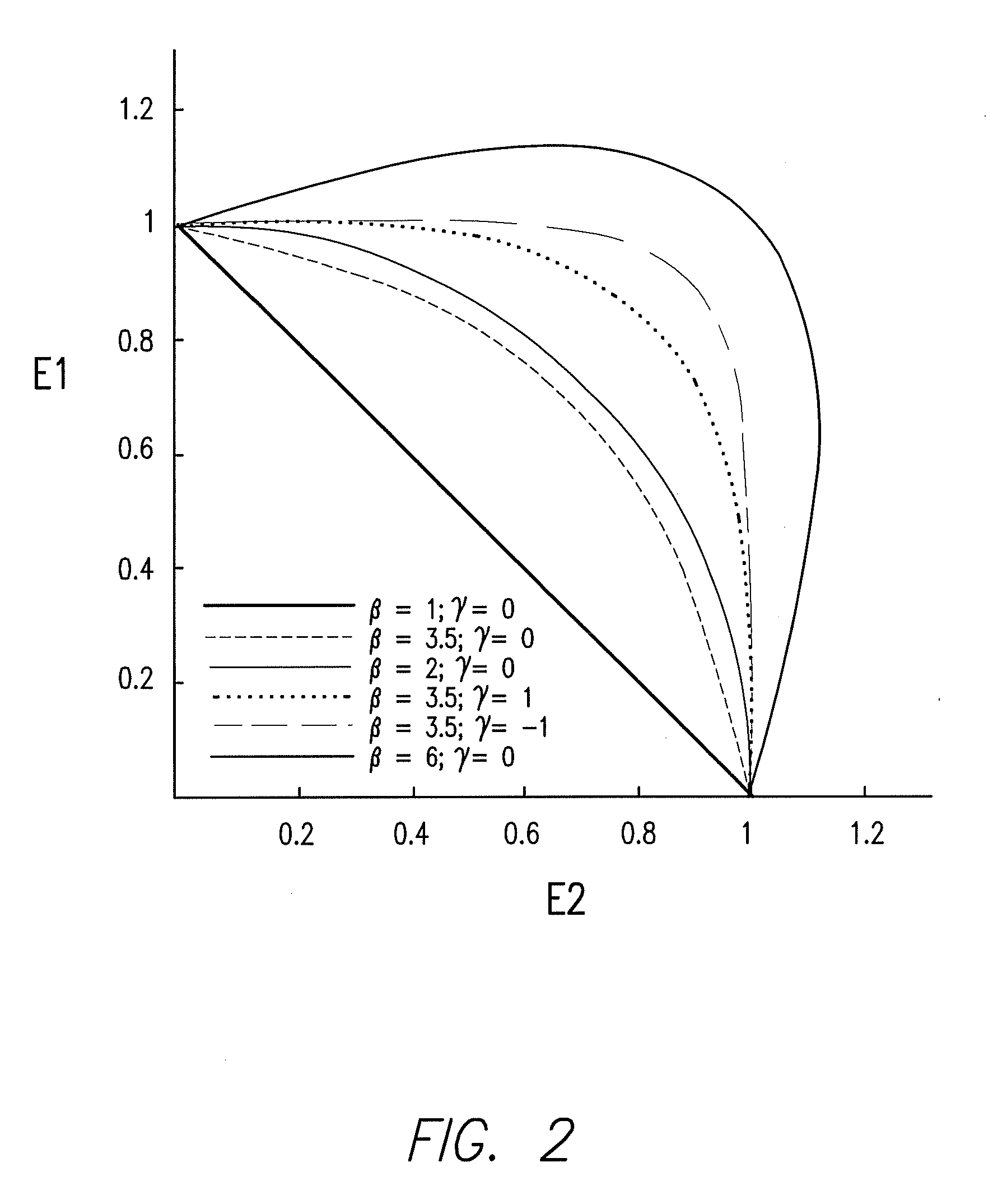
[0028]Methods: Subjects compared the brightness of a standard stimulus (where pulse trains across pairs of electrodes were synchronously presented) to the brightness of test stimuli (where pulse trains were phase-shifted by 0.075, 0.375, 1.8, or 9 ms). We measured the amount of total charge for each phase-shifted stimulus needed to make the test and the standard of equal brightness.

[0029]Results: Depending on the electrode pair, interactions between electrodes could be either facilitatory (the amount of charge need to match the brightness of the standard summed across electrodes) or suppressive (more charge was needed to match the brightness of the standard than would be required for either individual electrode alone). Data were fit with a simple, 2-parameter model. The amount of interaction between electrodes decreased both as a function of increasing time (phase-shift between pulse trains) and space (center-to-center distance between the electrode pair).

[0030]Conclusions: During m...


PUM


Abstract

The present invention is a method of stimulating visual neurons to create the perception of light. A visual prosthesis electrically stimulating the retina with implanted electrodes exhibits interaction between electrodes stimulated closely together in both space and time. The method of the present invention includes determining a minimum distance at which spatiotemporal interactions occur, determining a minimum time at which spatiotemporal interactions occur, and avoiding stimulation of electrodes within the minimum distance during the minimum time. The minimum are ideally established for each individual patient. Alternatively, approximate minimums have been established by the applicants at 2 mm and 1.8 μsec.

Description

CROSS REFERENCE TO RELATED APPLICATIONS[0001]This application claims priority to U.S. Provisional Application 61 / 298,836, filed Jan. 28, 2010, for Multielectrode Integration in a Visual Prosthesis, which is incorporated by reference.GOVERNMENT RIGHTS NOTICE[0002]This invention was made with government support under grant No. R24EY12893-01, awarded by the National Institutes of Health. The government has certain rights in the invention.FIELD OF THE INVENTION[0003]The present invention relates to visual prosthesis, and more particularly to apparatus and methods to compensate for integration of stimulation between geographically close electrodes.BACKGROUND[0004]Retinitis pigmentosa (RP) and age-related macular degeneration (AMD) are photoreceptor diseases that cause substantial vision loss and lead to subsequent blindness in over 15 million people worldwide. After the loss of the photoreceptor layer, the spatial organization of the inner nuclear and ganglion cell layers can become diso...

Claims


Application Information

Patent Timeline
IPC IPC(8): A61F9/08A61N1/36
CPCA61N1/36046A61N1/0543
Inventor HORSAGER, ALAN MATTHEWBOYNTON, GEOFFREY M.FINE, IONEGREENBERG, ROBERT J.
Owner CORTIGENT INC
Learn More