Method of providing electric current taker for support bar, and support bar

Active Publication Date: 2011-07-28
VALVAS
View PDF7 Cites 1 Cited by
  • Summary
  • Abstract
  • Description
  • Claims
  • Application Information

AI Technical Summary

Benefits of technology

[0006]An object of the invention is to provide a method which eliminates the above-mentioned problems of the prior art, or at least substantially alleviates them, and which enables an easy, quick and inexpensive manufacture of a support bar and an electric current taker thereto.
[0015]The most important advantages of the method according to the invention are that it enables the support bar to be provided with a highly electroconductive contact surface and an electric current taker in an easy and quick manner. The method is simple and easy enough to carry out to enable practically anyone with no special skills to perform it successfully. The method may be implemented very economically.
[0019]The most important advantages of the support bar according to the invention are that its electroconductivity and strength in the usage environment are very good while at the same time it is very inexpensive to implement.

Problems solved by technology

Further, the end result is not particularly good in terms of electroconductivity and strength since in practice it is very difficult to achieve a good metallurgic bond between aluminium and silver with good electroconductivity.
Prior to coating, the materials to be coated have to be cleaned from oxide layers e.g. by sandblasting or wire brushing since otherwise no good contact / joint can be obtained with the coating.
The cleaning work is time-consuming and does not always ensure a good end result.
Naturally, the thermal treatment adds to the amount of work.
The latter procedure is complicated.
The process of adhering the copper contact piece to the aluminium bar increases the manufacturing costs of the support bar.
It is difficult to attach the silver piece to the underlying aluminium surface.
All in all, the work requires a highly accurate performer and takes a lot of time.

Method used


Image

  • Method of providing electric current taker for support bar, and support bar
  • Method of providing electric current taker for support bar, and support bar

Examples


Embodiment Construction

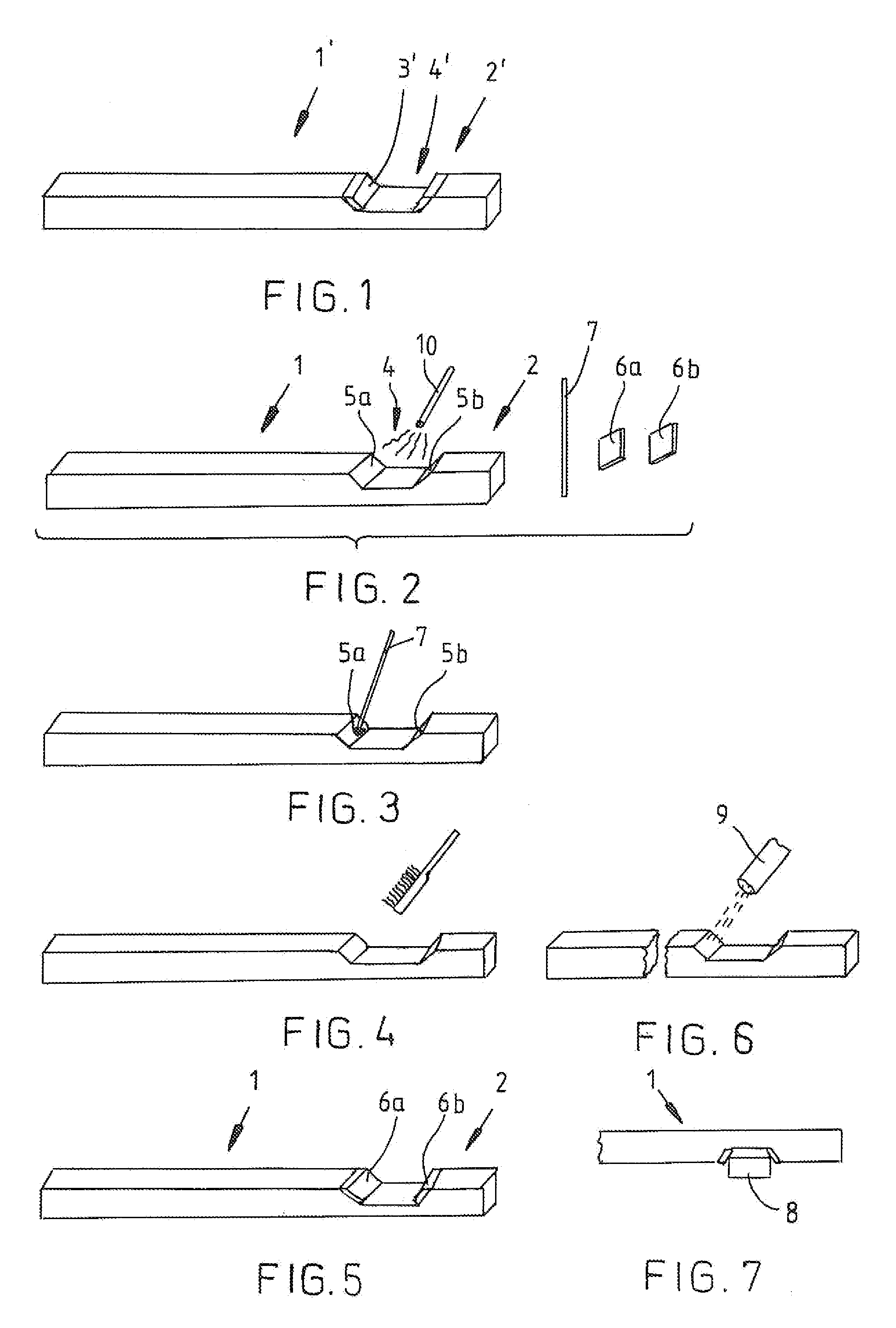
[0026]FIG. 1 shows a prior art support bar 1′. A first end 2′ of the support bar, which is made from aluminium, is provided with a copper contact piece 3′. The contact piece 3′ is attached to the aluminium support bar 1′ by friction welding. The contact piece 3′ forms a notch 4′ in the support bar. When the support bar 1′ of FIG. 1 is used in zinc electrolysis, an aluminiun cathode plate (not shown) is attached to the support bar (cathode bar) and the cathode plate is lowered supported by its support bar into an electrolysis basin (not shown) such that the contact piece 3′ of the support bar is placed on top of a busbar (cf. FIG. 7, part 8) provided on the edges of the electrolysis basin so that the busbar settles in the notch 4′ and a second end of the support bar settles on top of an insulator (not shown). The contact piece 3′ constitutes an electric current taker of the support bar. The contact of the contact piece 3′ to the busbar having an angular cross section is formed of two...


PUM

PropertyMeasurementUnit
Temperatureaaaaaaaaaa
Percent by massaaaaaaaaaa

Abstract

The invention relates to a method of providing an electric current taker made from silver and having a highly electroconductive contact surface into an aluminium support bar to be used in electrolysis. In order for the support bar and the electric current taker therein to be easily, quickly and inexpensively manufactured, the method comprises a) heating a first end of the support bar and providing on top of it a solder containing a substance whose affinity to oxygen is high after a temperature of an aluminium surface is at a temperature which exceeds a melting temperature of the solder, whereby the solder is spread in a molten state on top of the surface, b) breaking an aluminium oxide layer between the aluminium and the molten solder by a mechanical treatment so that oxygen is released from the aluminium oxide layer, the oxygen reacting with the substance of the solder having a high affinity to oxygen and forming, together with the substance, on the surface of the molten solder an oxide layer, and c) providing, on top of the solder, the electric current taker and letting the solder to solidify and the electric current taker to become attached to the solidified solder. The invention further relates to a support bar.

Description

BACKGROUND OF THE INVENTION[0001]The invention relates to a method of providing an electric current taker made from silver or silver-based alloy and having a highly electroconductive contact surface onto a surface of a first end of an aluminium support bar to be used in electrolysis, which support bar via the electric current taker is to be supported against a busbar used in connection with an electrolysis basin.[0002]The invention also relates to an aluminium support bar to be used in electrolysis, whose first end comprises an electric current taker made from silver or silver alloy and having a highly electroconductive contact surface, which support bar via the electric current taker is to be supported against a busbar used in connection with an electrolysis basin.[0003]From FI patent publication 114926 a method is known wherein an electric current taker made from silver or silver alloy is provided at an end of a support bar by coating, using thermal spray coating. The electric cur...

Claims


Application Information

Patent Timeline
IPC IPC(8): C25B9/02C23C8/80
CPCC25C7/02B23K1/0016B23K35/0227B23K35/282B23K2101/38B23K2103/10B23K2103/18C22C18/00C22C18/04
Inventor HAGNER, NIKO
Owner VALVAS
Why Eureka
Try Eureka