
Methods and apparatus for wireless RFID cardholder signature and data entry

a wireless rfid card and cardholder technology, applied in the field of rfid data cards, can solve the problems that the credit card that is electronically read may be targeted for theft and misuse, and achieve the effects of improving the accuracy of the location detection mechanism, reducing the cost of implementation, and reducing the risk of th

Inactive Publication Date: 2006-09-05
MASSACHUSETTS INST OF TECH
View PDF9 Cites 82 Cited by
  • Summary
  • Abstract
  • Description
  • Claims
  • Application Information

AI Technical Summary

Benefits of technology

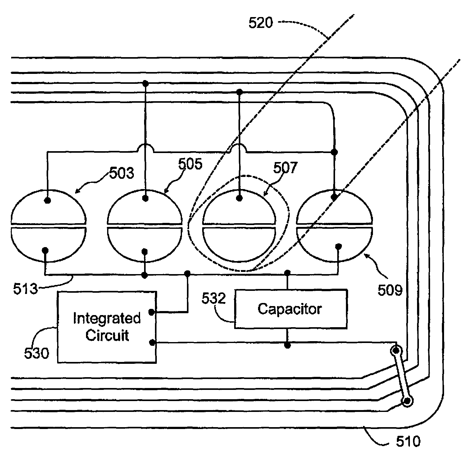
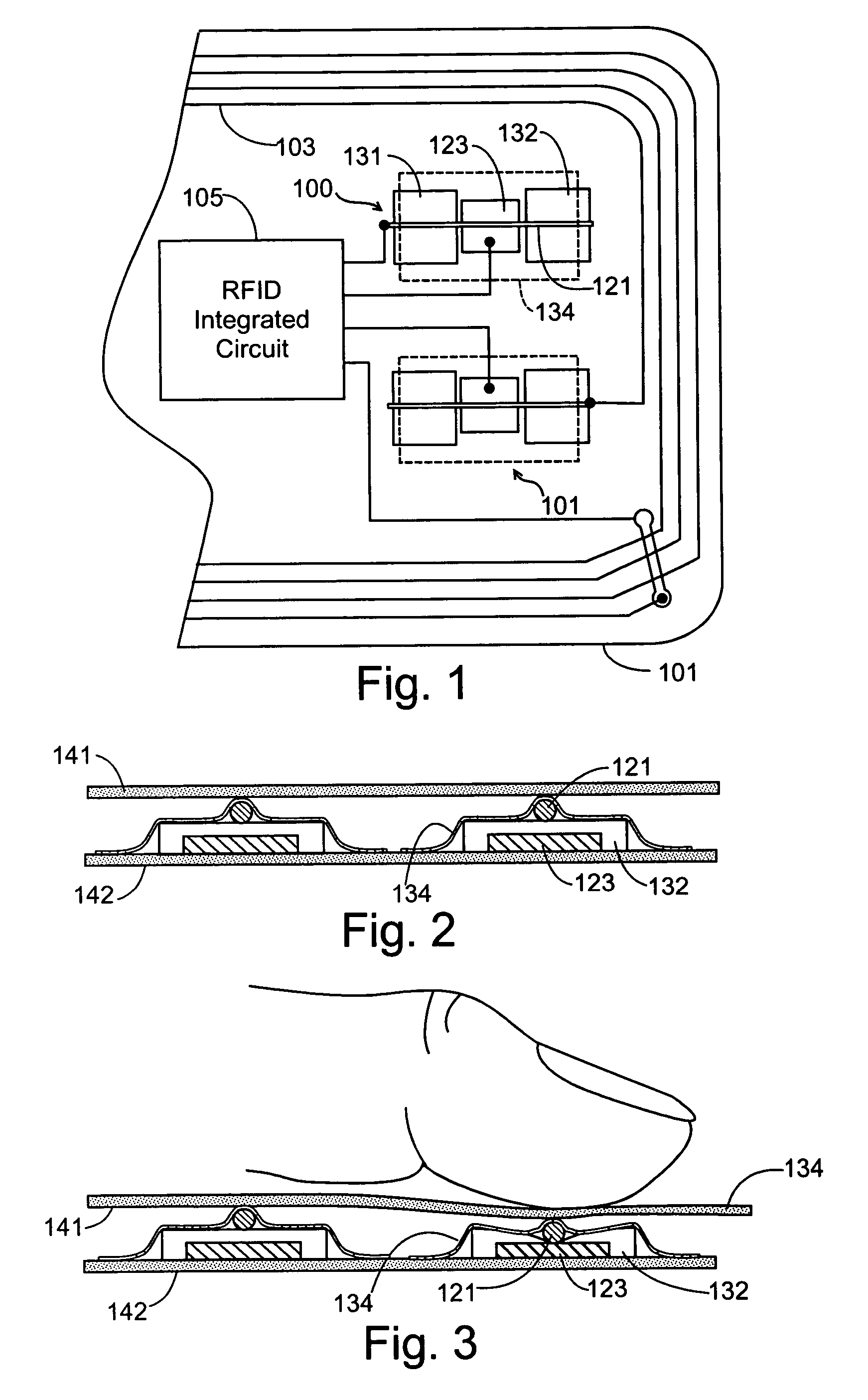
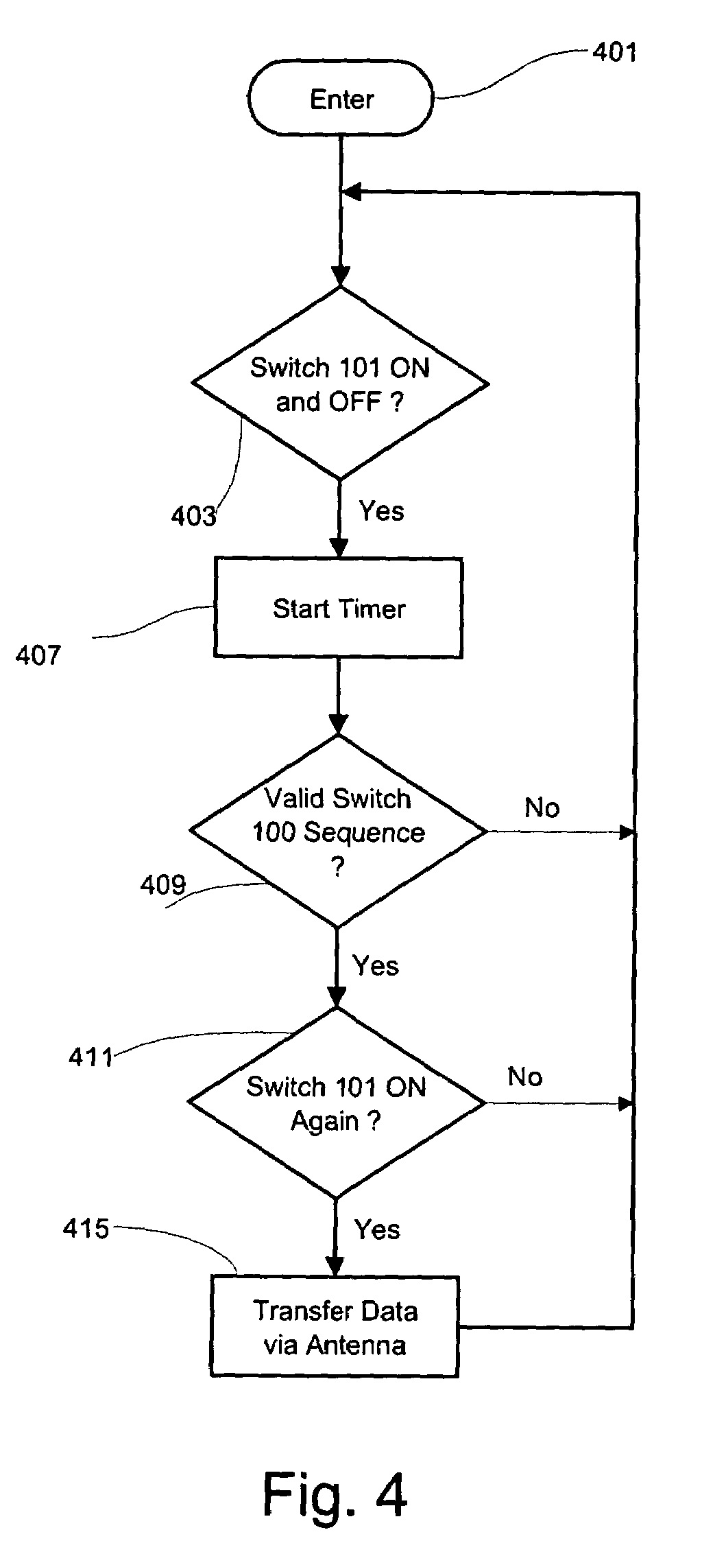
[0018]The on-card switching element(s), or the object position sensor(s), can be used to identify the person's “signature” of finger motions on the card for personal identification, the switching element(s) and / or sensor(s) may also form virtual or actual buttons, sliders, a keypad, etc. on the card which permit the cardholder to activate the card or enter data. The use of a conductive stylus or other conductive object designed to disturb the electrical, magnetic or electromagnetic properties of the card may be used instead of the cardholder's finger or hand to improve the precision of the location detection mechanism.
[0019]The electrical switching elements used to perform these functions can be implemented inexpensively using mechanism which require few if any mechanical parts for measuring the proximity of the user's hand, finger, thumb or other conductive member with respect to predetermined areas on the card. By using a sensing mechanism that effects the gain or resonant frequency of the antenna, the sensing function may be performed as a part of signal transmission and can be implemented either on the card or the card reader, and enables the cardholder to identify herself without requiring a complex biometric sensor.

Problems solved by technology

Electronically read credit cards may be targeted for theft and misuse.

Method used


Image

  • Methods and apparatus for wireless RFID cardholder signature and data entry
  • Methods and apparatus for wireless RFID cardholder signature and data entry
  • Methods and apparatus for wireless RFID cardholder signature and data entry

Examples


Embodiment Construction

[0033]RF-enabled cards, identification tags, security passkeys and the like (hereinafter collectively referred to as “cards” or “data cards”) carry data which typically identifies or relates to a specific person, a particular account, an individual vehicle, or a particular item, and further contains additional data supporting applications through item specific information or instructions that can be made immediately available by reading the card.

[0034]A RFID system requires, in addition to the data cards, a means of reading or interrogating the data cards and communicating data between the card and a host computer or an information management system (hereinafter referred to as a “reader”). Communication of data between the cards and a reader is achieved by wireless communication, either based upon close proximity electromagnetic or inductive coupling, or based upon propagating electromagnetic waves. Coupling is achieved using antenna structures forming an integral feature in both da...


PUM


Abstract

A radio operated data card whose outer jacket forms a sealed protected housing for internal electrical components, including an RFID integrated circuit which incorporates data storage and a radio frequency transceiver, and one or more on-card antenna structures. Manually operated electrical switching elements, or antenna structures which are responsive to the positioning of conductive members, such as the human hand, at particular locations on or near the surface of the card, are connected to the on-card electronic circuitry. The switching elements or antenna elements are selectively operated by the cardholder who manipulates the card in predetermined ways to generate data signals that may be used to activate the card, store data in the card, or transmit data to the reader.

Description

CROSS REFERENCE TO RELATED APPLICATIONS[0001]This application is a continuation impart of U.S. patent application Ser. No. 10 / 334,572 filed Dec. 31, 2002, now U.S. Pat. No. 6,863,220 issued Mar. 8, 2005, the disclosure of which is hereby incorporated herein by reference.FIELD OF THE INVENTION[0002]This invention relates to radio frequency identification (RFID) systems and more particularly to RF data cards carried by cardholders.BACKGROUND OF THE INVENTION[0003]Electronically read credit cards may be targeted for theft and misuse. Readily available card readers can be used by a thief to obtain account information from the card. While magnetic strip and contact-bearing cards are protected to some extent by the fact that the card must be in physical contact with the reader, contactless cards that use radio signaling to exchange information with a host system can be used without bringing it into direct contact with a reader. Because such contactless devices can be read at a distance wi...

Claims


Application Information

Patent Timeline
Patent Type & Authority Patents(United States)
IPC IPC(8): G06K19/06G06K7/08G06K19/073G06K19/077
CPCG06K19/0716G06K19/07345G06K19/07749H01H2239/076H01H2231/05G06K19/06
Inventor SELKER, EDWIN JOSEPH
Owner MASSACHUSETTS INST OF TECH
Learn More