Method For Improving Hydraulic Fracturing Efficiency And Natural Gas Production

Active Publication Date: 2011-07-28
WATER TECTONICS
View PDF99 Cites 21 Cited by
  • Summary
  • Abstract
  • Description
  • Claims
  • Application Information

AI Technical Summary

Benefits of technology

[0013]The EC treatment serves to reduce the viscosity of the fracturing fluid, which makes it function better in the underground or producing formation. Part of the viscosity improvement obtained via the EC treatment process relates to bacterial content removal and reduction in turbidity, in addition to removal of other particulates.
[0015]The EC system uses the combination of a variable power supply, step-down transformer(s), and an AC to DC rectifier to produce the required treatment conditions (proper electric current level). The design reduces the overall power consumed by EC cells in order to achieve clarity in the treated water over a wide range of water conductivity.
[0017]Based on results to date, the methods and processes disclosed here will significantly reduce conventional transportation and disposal costs attributable to water hauling and treatment in hydraulic fracturing operations. Moreover, the desired water quality is achieved at lowered electrical cost relative to known EC systems. Finally, use of the methods and processes disclosed here appear to generate better flow back return from the well, and increased natural gas production, because EC treatment at the well head site decreases the volume of particles in the fluid that would otherwise be trapped in the fracture. EC treatment at the well head site also helps to reduce the ability of the water to form scales and precipitants while reacting with formation and other metals and minerals in the fracturing water. Not only does it immediately enhance production but it also improves the production life of the well. EC treatment provides other potential benefits such as overall reduction in proppant / chemical use and minimizing environmental impact because of better point-source control of contaminated water.

Problems solved by technology

Even though it is relatively clean, newly delivered fresh water may still contain bacterial or other contaminants that impede the fracturing process.

Method used


Image

  • Method For Improving Hydraulic Fracturing Efficiency And Natural Gas Production
  • Method For Improving Hydraulic Fracturing Efficiency And Natural Gas Production
  • Method For Improving Hydraulic Fracturing Efficiency And Natural Gas Production

Examples


Embodiment Construction

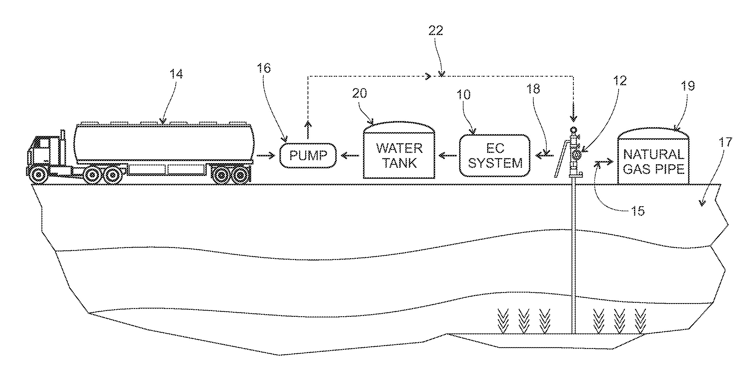
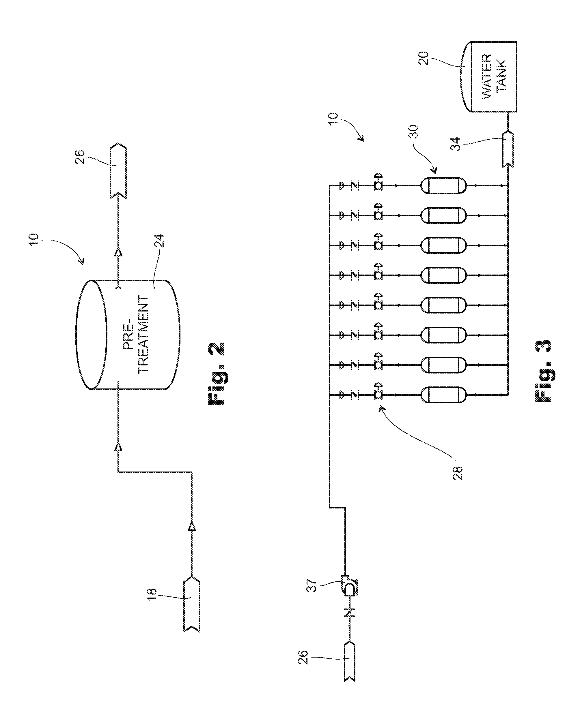
[0027]Referring first to FIG. 1, the general process will now be described. The process centers around the use of a portable electrocoagulation (“EC”) system 10 (further described below) that is brought to a natural gas well head site 12. The EC system 10 is small enough to rest on a truck trailer bed (not shown in the drawings).

[0028]Referring to FIG. 8, as an example, water that is to be used in the hydraulic fracturing operation is delivered to the well head site, as schematically indicated at 14 (by truck or other means). Newly delivered water (reference 13) is processed by the EC system 10 and then mixed with proppant particulates. It is then pumped (as illustrated at 16) down the bore at the well head location, thus introducing a hydraulic fracturing fluid into a subterranean formation (indicated at 17). This basic fracturing process is well-known in the gas industry, with the exception of using EC technology. Likewise, many different variations on the make-up and delivery of ...


PUM

PropertyMeasurementUnit
Flow rateaaaaaaaaaa
Viscosityaaaaaaaaaa
Ratioaaaaaaaaaa

Abstract

A method of improving natural gas release from a well via an enhanced hydraulic fracturing operation. The method includes capturing or retrieving the flow back from the well following the fracturing operation. The flow back or other source water is introduced to an electrocoagulation (“EC”) treatment process. EC treatment separates the water from other fracturing fluid components in the flow back and also removes bacteria and other contaminants. Thereafter, the EC-treated fluid is recycled for subsequent fracturing operations. The process may also be used to treat all source water, including fresh water delivered to the well before it is used as a fracturing fluid.

Description

TECHNICAL FIELD[0001]The invention disclosed here generally relates to hydraulic fracturing methods for enhancing the production of a natural gas well. More specifically, the invention is directed to a method of enhancing the fracturing and natural gas release process by pre-treating water used in the fracturing fluid and / or recycling treated flow back fluid or source water previously used in the hydraulic fracturing process.BACKGROUND OF THE INVENTION[0002]“Hydraulic fracturing” is a common and well-known enhancement method for stimulating the production of natural gas. The process involves injecting fluid down a well bore at high pressure. The fracturing fluid is typically a mixture of water and proppant (the term “proppant” includes sand and synthetics). Other chemicals are often added to the proppant to aid in proppant transport, friction reduction, wettability, pH control and bacterial control.[0003]Varying amounts of water are required in a typical hydraulic fracturing operati...

Claims


Application Information

Patent Timeline
IPC IPC(8): E21B43/26
CPCC02F1/001E21B43/40C02F1/463C02F1/52C02F9/00C02F2103/10C02F2209/001C02F2209/003C02F2209/006C02F2209/06C02F2209/11C02F2209/40E21B43/26C02F1/008E21B43/35
Inventor MOTHERSBAUGH, JAMESHANCOCK, GENE
Owner WATER TECTONICS
Why Eureka
Try Eureka