
Minature sludge lance apparatus

a technology of miniaturized sludge and lance, which is applied in the direction of lighting and heating equipment, machines/engines, flush cleaning, etc., can solve the problems of inability to clean equipment, sludge between close patterns, and less effective at locations separated from the tube lane, etc., to achieve quick, accurate, repeatable setup

Active Publication Date: 2011-07-28
WESTINGHOUSE ELECTRIC CORP
View PDF12 Cites 4 Cited by
  • Summary
  • Abstract
  • Description
  • Claims
  • Application Information

AI Technical Summary

Benefits of technology

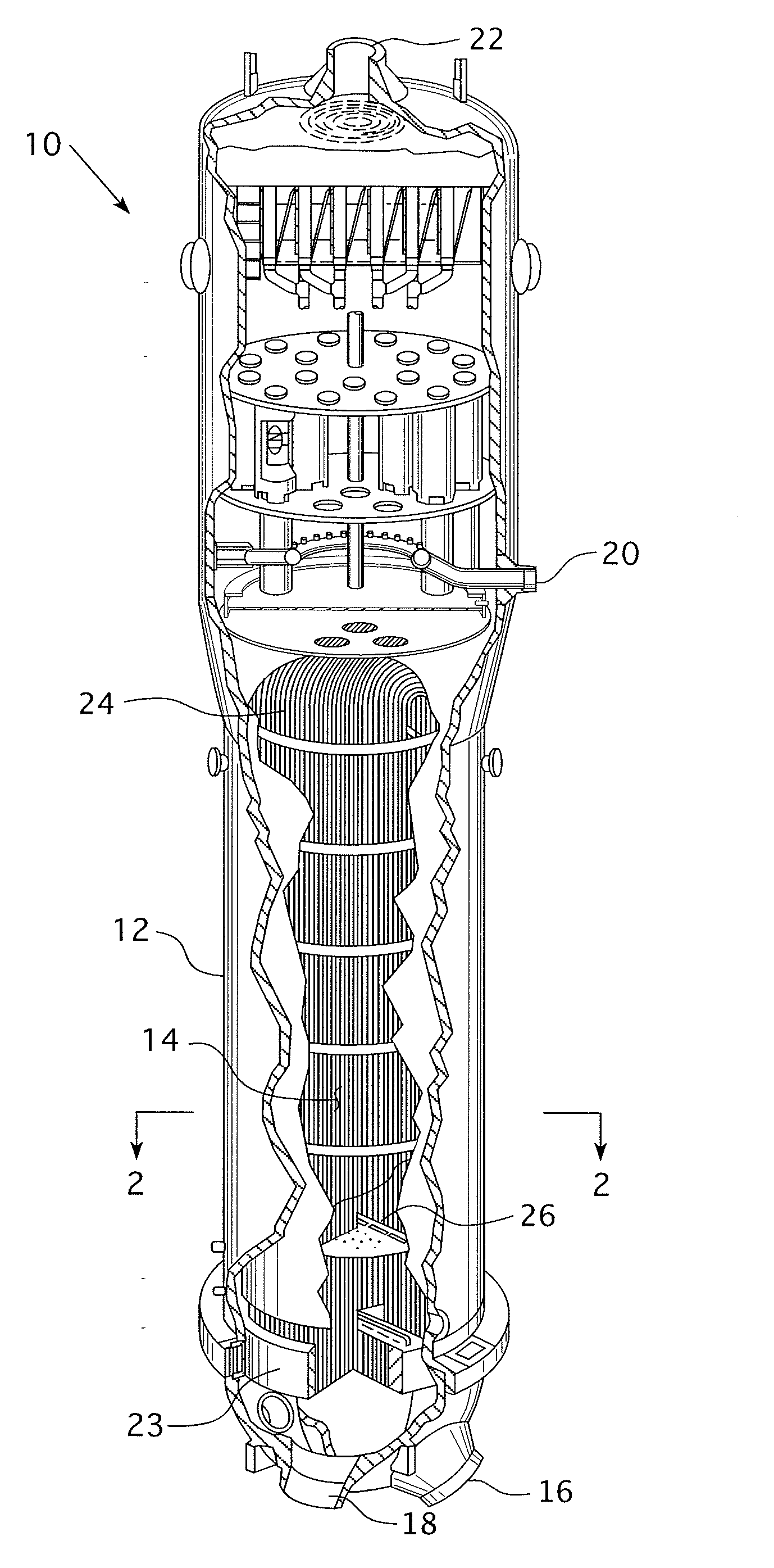
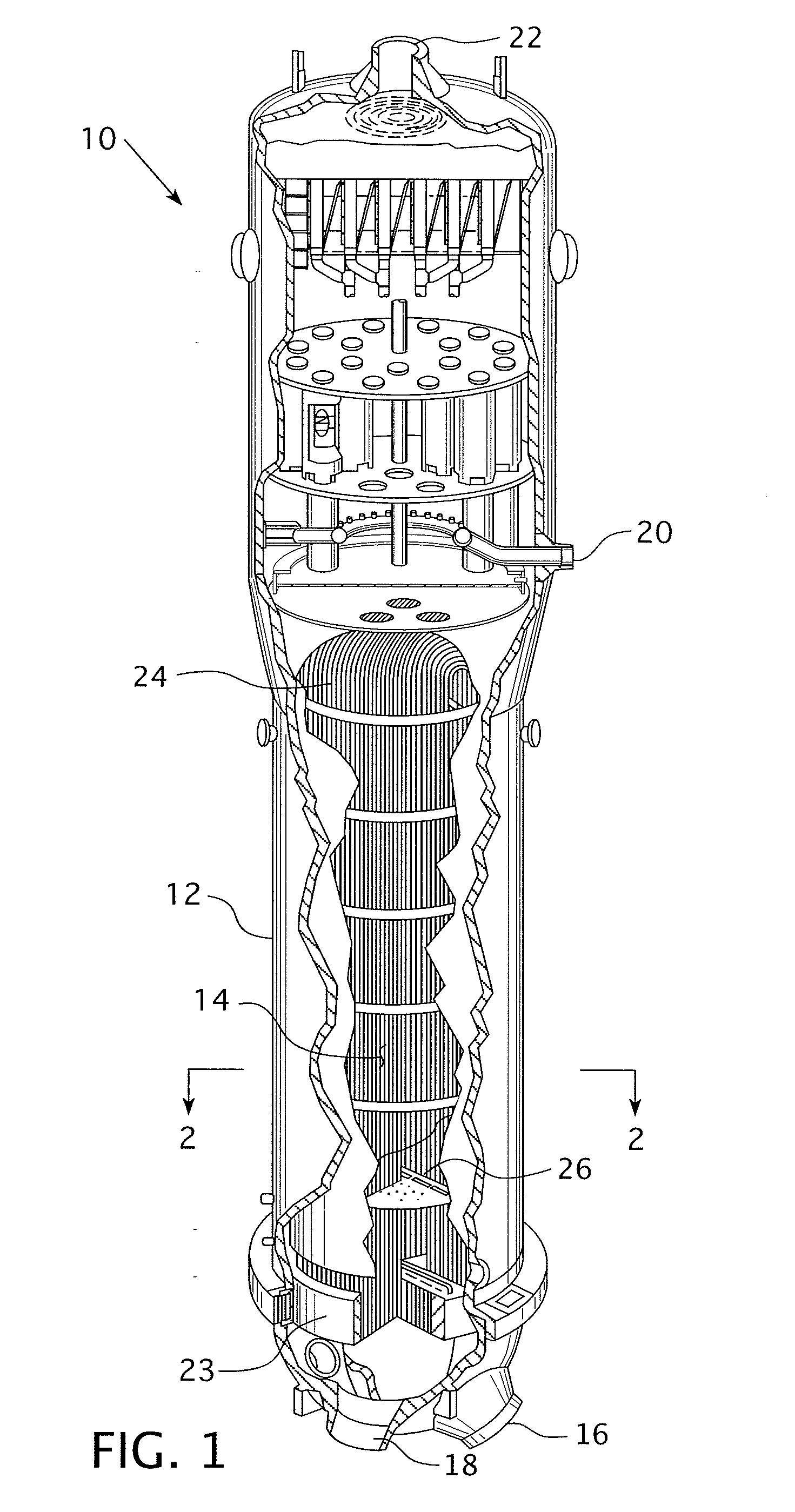
The patent describes a system for cleaning the insides of a steam generator by using a high-velocity water jet to remove sludge and debris. The system includes a sludge lance that can be automatically indexed relative to the tube bundle spacing and a rail system that supports and moves the lance. The system can be easily installed and can reduce the time required for sludge lancing, lowering the radiological dose. The technical effects of the patent include efficient and effective cleaning of the steam generator, reduced risk of accidents, and improved safety and reliability.

Problems solved by technology

This cleaning pattern, however, may leave sludge between the close pattern of tubes and is less effective at locations spaced from the tube lane.
The tube lane blocks can prohibit access for cleaning equipment through the six inch penetration.
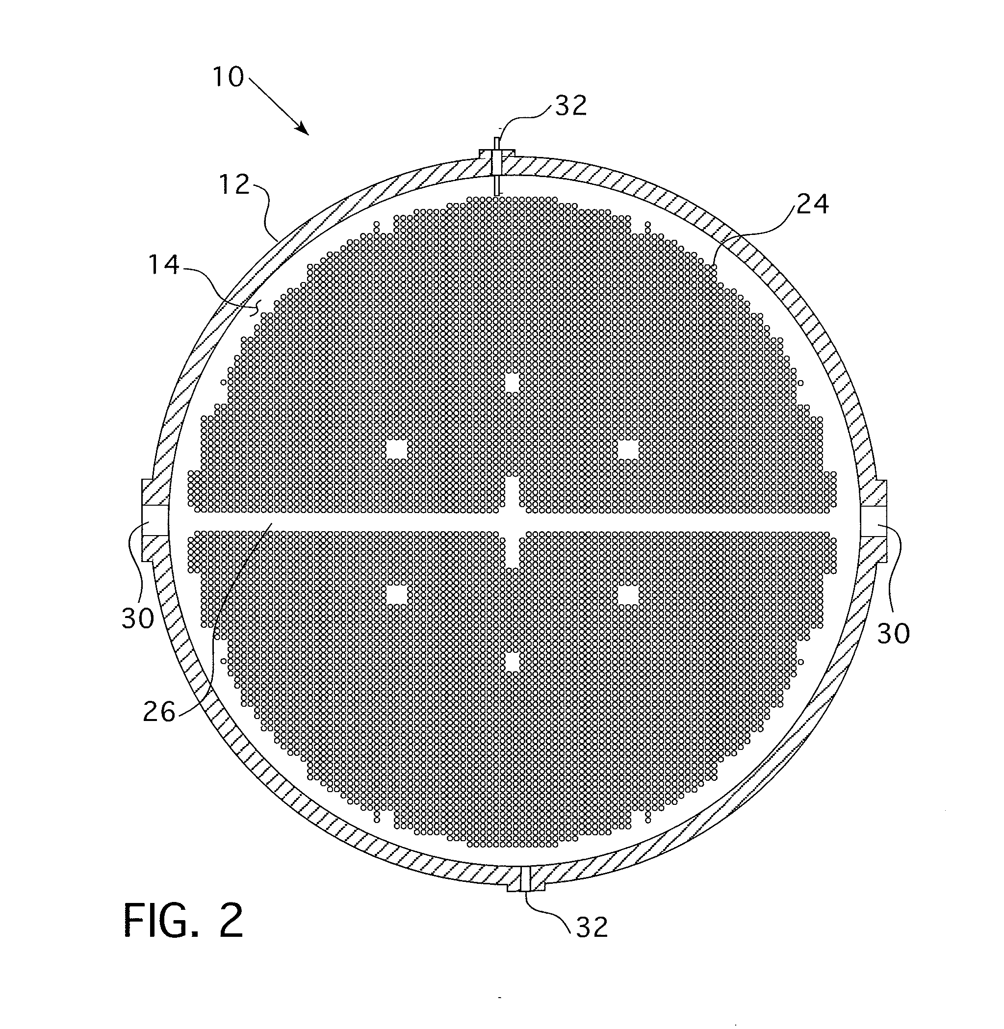
Due to various internal physical restrictions in the tube lane (the area generated along the centerline of the tube sheet by the minimum bend radius of the Row 1 tubes), the tube sheet legs (either hot or cold depending on the location of the inlet nozzle) cannot be adequately cleaned by conventional lancing equipment mounted to the hand holes.
After entrance through an inspection penetration, access is limited by the gap between adjacent tubes.
These openings are not typically used for cleaning because the problem is to accurately position and sweep high pressure cleaning jets and deliver high water volume within the confines of adjacent tube spacing and the inspection penetration.
Sludge lancing is typically not performed through these penetrations due to their physical size and location.
Therefore, the tube lane in these steam generators is basically inaccessible and prone to accumulating sludge and debris under the blowdown pipe and between the TLBD's.
In addition, certain utilities have forbidden hand-lancing with static jets that impinge directly on the tube sheet and adjacent steam generator tubing—this limits certain types of manual lancing that could be employed through the inspection penetrations to clean this region.
Sludge lancing technicians are subjected to higher doses or radiation with equipment that does not provide an automated mechanical means of oscillation or rotation of the high velocity jets down the tube gaps.
Water turbulence from a 90 degree bend significantly increases the divergence of the exiting water jet.

Method used


Image

  • Minature sludge lance apparatus
  • Minature sludge lance apparatus
  • Minature sludge lance apparatus

Examples


Embodiment Construction

[0047]As used herein, “coupled” means a link between two or more elements, whether direct or indirect, so long as a link occurs.

[0048]As used herein, “directly coupled” means that two elements are directly in contact with each other.

[0049]As used herein, “fixedly coupled” or “fixed” means that two components are coupled so as to move as one while maintaining a constant orientation relative to each other. The fixed components may, or may not, be directly coupled.

[0050]As used herein, “temporarily coupled” means that two components are coupled in a manner that allows for the components to be easily decoupled without damaging the components. “Temporarily coupled” components are easy to access or otherwise manipulate. For example, a nut on a bolt that is exposed is “temporarily coupled” while a nut on a bolt within a typical transmission case sealed by multiple fasteners is not “temporarily coupled.”

[0051]As used herein, “correspond” indicates that two structural components are sized to...


PUM


Abstract

A miniature sludge lance for a steam generator in a pressurized water nuclear reactor is provided. The sludge lance is structured to enter the steam generator via an inspection opening and has a body sufficiently thin to fit between adjacent tubes. The sludge lance rail has at least two types of nozzle assemblies that may be attached thereto. One nozzle assembly rotates and another nozzle assembly translates in a vertical direction. A drive assembly, a mounting assembly, an oscillation assembly, and flow straighteners are also provided.

Description

CROSS REFERENCE TO RELATED APPLICATIONS[0001]This application is a continuation application of application Ser. No. 12 / 938,027, filed Nov. 2, 2010, entitled MINIATURE SLUDGE LANCE APPARATUS, which claims priority from provisional application Ser. Nos. 61 / 257,584, filed Nov. 3, 2009, entitled MINIATURE SLUDGE LANCE APPARATUS; 61 / 258,794, filed Nov. 6, 2009, entitled HAMMERHEAD; and 61 / 257,597, filed Nov. 3, 2009, entitled MINIATURE NOZZLE FLOW STRAIGHTENER FOR 90 DEGREE BEND.BACKGROUND OF THE INVENTION[0002]1. Field of the Invention[0003]This invention relates to a cleaning device for a steam generator and, more specifically, to a miniature sludge lance structured to pass between adjacent tubes in the steam generator.[0004]2. Description of the Prior Art[0005]A pressurized water nuclear reactor utilizes a steam generator to maintain separation of the water that passes over the nuclear fuel (the “primary water”) and the water that passes through the electricity generating turbines (th...

Claims


Application Information

Patent Timeline
Patent Type & Authority Applications(United States)
IPC IPC(8): F28G9/00
CPCF22B37/003F22B37/483F28G15/04F28G3/166F28D7/06
Inventor HAWKINS, PHILLIP J.HABERMAN, ERIC R.RUDISH, JEROD J.SELFRIDGE, DAVID W.
Owner WESTINGHOUSE ELECTRIC CORP
Learn More