
Time warp activation signal provider, audio signal encoder, method for providing a time warp activation signal, method for encoding an audio signal and computer programs

a technology of activation signal and time warp, applied in the field of audio encoding and decoding, can solve the problems of reducing coding efficiency, time warping is not always successful in improving coding efficiency, time warping does not improve coding efficiency, etc., and achieves significant gain in bitrate/quality, improved quality, and reduced gain in quality/bitrate provided by tns tools.

Active Publication Date: 2011-07-21
FRAUNHOFER GESELLSCHAFT ZUR FOERDERUNG DER ANGEWANDTEN FORSCHUNG EV
View PDF29 Cites 133 Cited by
  • Summary
  • Abstract
  • Description
  • Claims
  • Application Information

AI Technical Summary

Benefits of technology

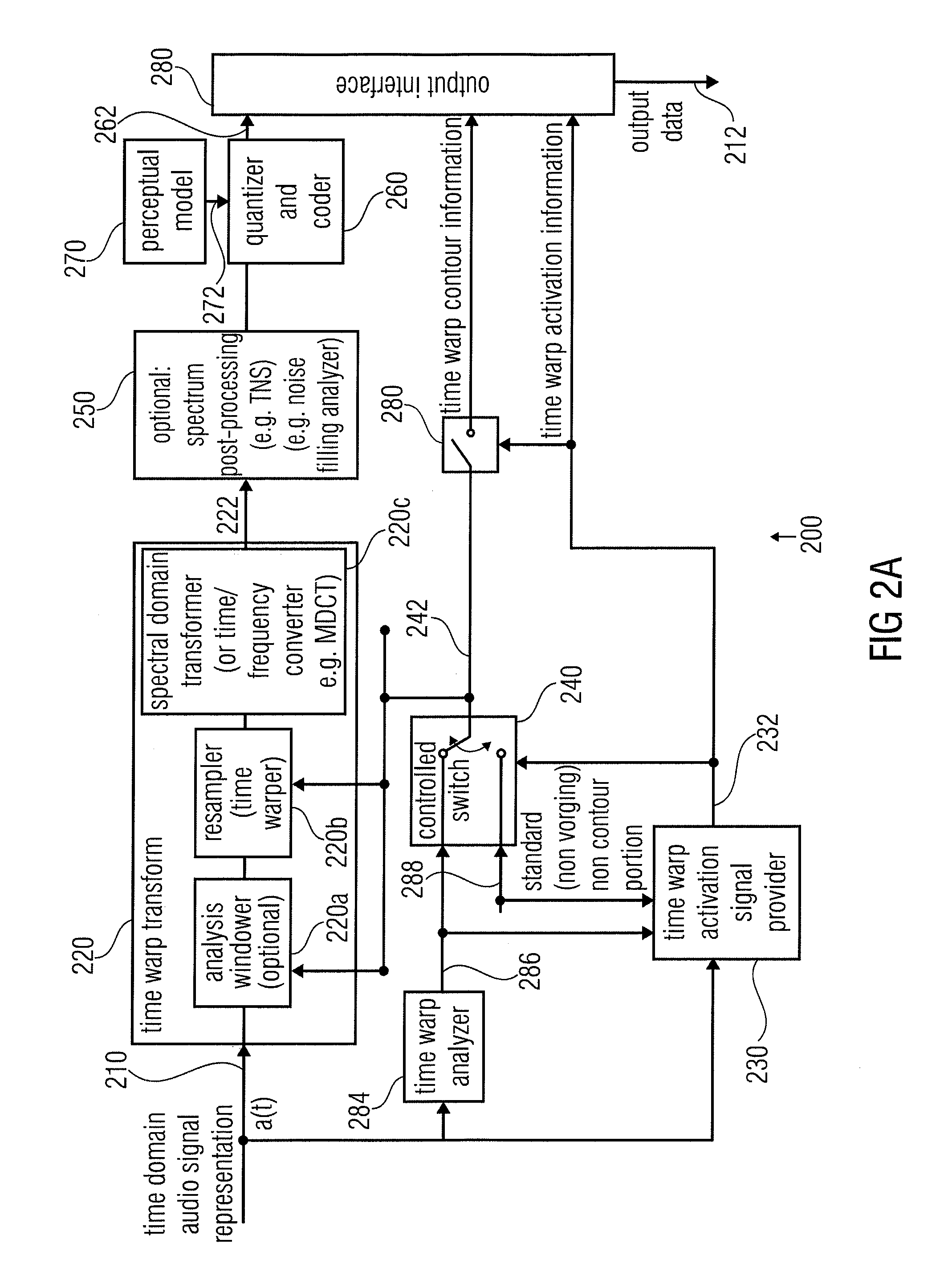
[0024]According to another embodiment, an audio encoder for encoding an audio signal may have a time warper for warping an audio signal using a variable time warping characteristic; a time / frequency converter for converting a time warped audio signal into a spectral representation having a number of spectral coefficients; and a processor for processing a variable number of spectral coefficients to generate an encoded audio signal, wherein the processor is configured for variably setting a number of spectral coefficients for a frame of the audio signal based on the time warping characteristic for the frame so that a bandwidth variation represented by the processed number of frequency coefficients from frame to frame is reduced or eliminated.
[0057]Therefore, without the inventive modification of the TNS tool, time-warped portions typically would not be TNS processed, but would be processed without a TNS filtering. On the other hand, the noise shaping feature of TNS nevertheless provides an improved quality specifically in situations, where the signal is varying in amplitude / power. In cases, where an onset of an harmonic signal or speech signal is present, and where the block switching feature is implemented so that, instead of this onset, long windows or at least windows longer than short windows are maintained, the activation of the temporal noise shaping feature for this frame will result in a concentration of the noise around the speech onset which effectively reduces pre-echoes, which might occur before the onset of the speech due to a quantization of the frame occurring in a subsequent encoder processing.

Problems solved by technology

For signals with varying pitch, however, the energy corresponding to each harmonic component is spread over several transform coefficients, thus leading to a reduction of coding efficiency.
Nevertheless, time warping is not always successful in improving the coding efficiency.
For example, time warping does not improve the coding efficiency if the input audio signal comprises large noise components, or if the extracted time warp contour is inaccurate.
In contrast, if the time warped time domain signal does not comprise a significant periodicity, it can be concluded that the time warping is not efficient.
In contrast, if the time warping is not capable of providing a time domain signal having a high degree of periodicity, it can be expected that the time warping also does not provide a significant bitrate saving, which would justify its application.
It has been found that a computationally complex determination of the autocorrelation peaks is not needed to estimate the efficiency of the time warping.
This concept is based on the finding that it is not always efficient to introduce a time warp information into an encoded representation of the input audio signal, because a remarkable number of bits is needed for encoding the time warp information.
These short windows, however, have a correspondingly reduced frequency resolution which, on the other hand, would decrease the coding gain for strongly harmonic signals and therefore increase the number of bits needed to code such signal portion.
However, harmonic signals will, normally, not be suitable for being subjected to the TNS processing.

Method used


Image

  • Time warp activation signal provider, audio signal encoder, method for providing a time warp activation signal, method for encoding an audio signal and computer programs
  • Time warp activation signal provider, audio signal encoder, method for providing a time warp activation signal, method for encoding an audio signal and computer programs
  • Time warp activation signal provider, audio signal encoder, method for providing a time warp activation signal, method for encoding an audio signal and computer programs

Examples


Embodiment Construction

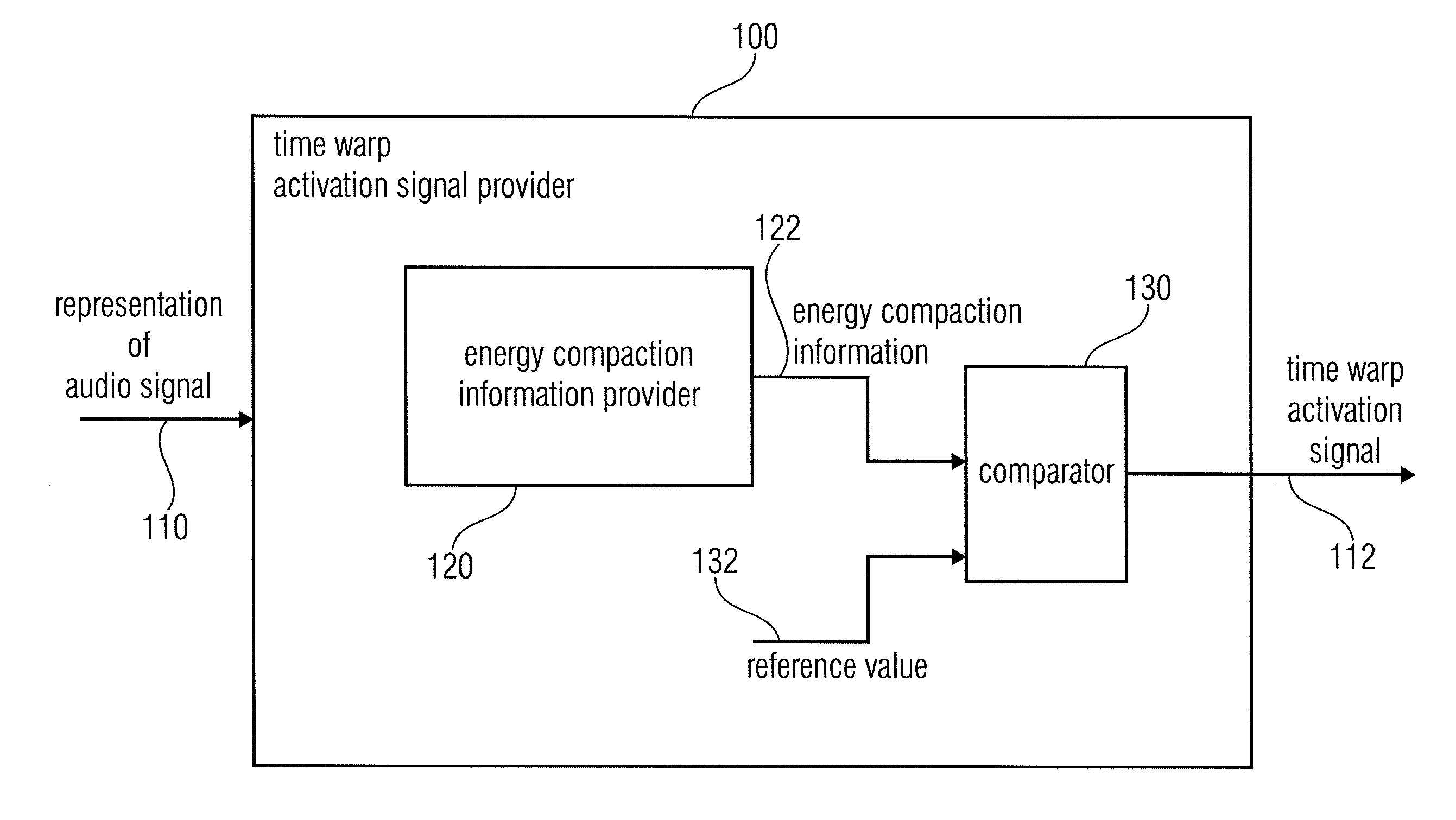
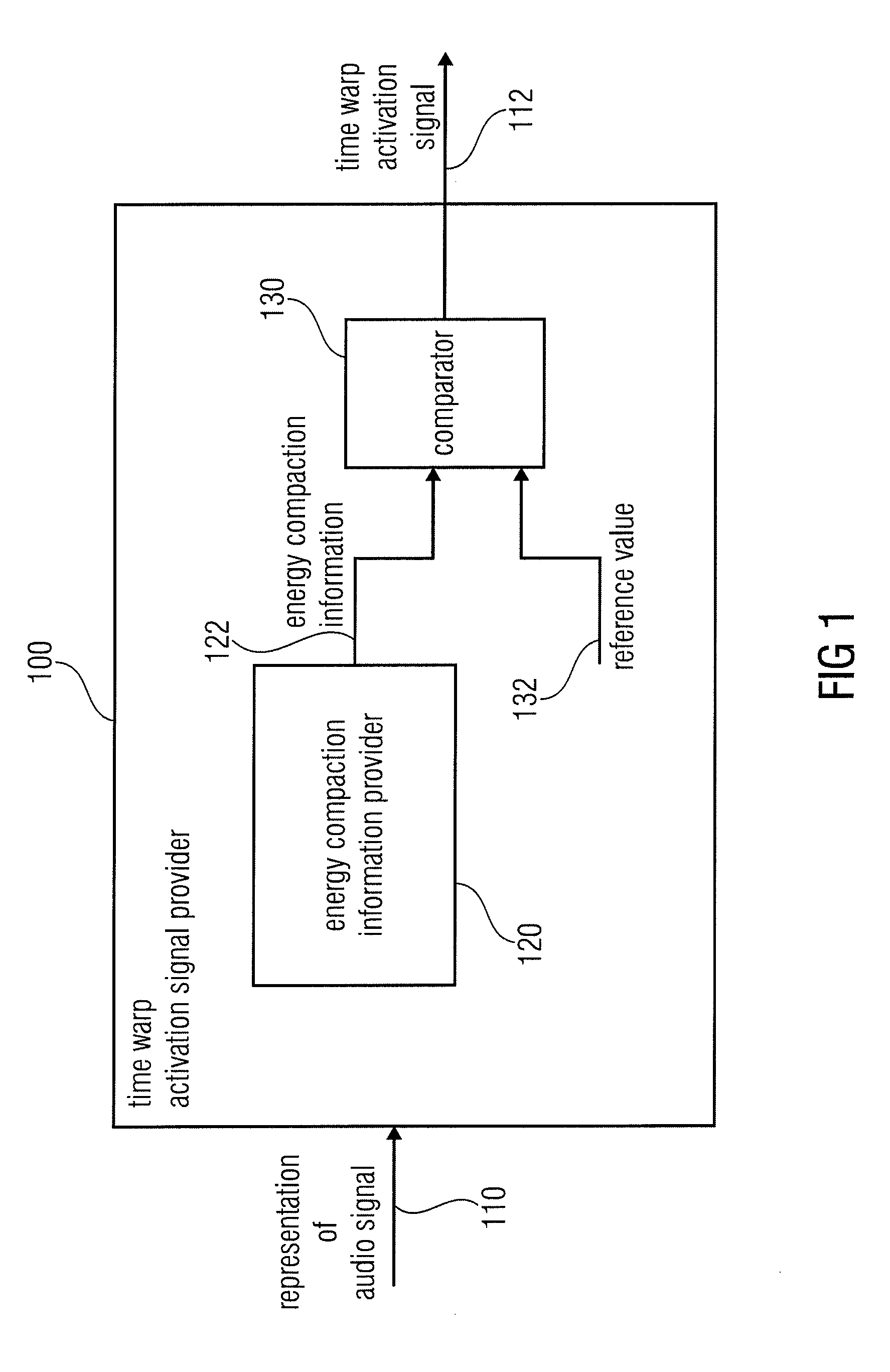
[0093]FIG. 1 shows a block schematic diagram of the time warp activation signal provider, according to an embodiment of the invention. The time warp activation signal provider 100 is configured to receive a representation 110 of an audio signal and to provide, on the basis thereof, a time warp activation signal 112. The time warp activation signal provider 100 comprises an energy compaction information provider 120, which is configured to provide an energy compaction information 122, describing a compaction of energy in a time warp transformed spectrum representation of the audio signal. The time warp activation signal provider 100 further comprises a comparator 130 configured to compare the energy compaction information 122 with a reference value 132, and to provide the time warp activation signal 112 in dependence on the result of the comparison.

[0094]As discussed above, it has been found that the energy compaction information is a valuable information which allows for a computati...


PUM


Abstract

An audio encoder has a window function controller, a windower, a time warper with a final quality check functionality, a time / frequency converter, a TNS stage or a quantizer encoder, the window function controller, the time warper, the TNS stage or an additional noise filling analyzer are controlled by signal analysis results obtained by a time warp analyzer or a signal classifier. Furthermore, a decoder applies a noise filling operation using a manipulated noise filling estimate depending on a harmonic or speech characteristic of the audio signal.

Description

CROSS-REFERENCE TO RELATED APPLICATIONS[0001]This application is a continuation of copending International Application No. PCT / EP2009 / 004874, filed Jul. 6, 2009, which is incorporated herein by reference in its entirety, and additionally claims priority from U.S. Patent Application No. 61 / 079,873 filed Jul. 11, 2008, which is incorporated herein by reference in its entirety.BACKGROUND OF THE INVENTION[0002]The present invention is related to audio encoding and decoding and specifically for encoding / decoding of audio signal having a harmonic or speech content, which can be subjected to a time warp processing.[0003]In the following, a brief introduction will be given into the field of time warped audio encoding, concepts of which can be applied in conjunction with some of the embodiments of the invention.[0004]In the recent years, techniques have been developed to transform an audio signal into a frequency domain representation, and to efficiently encode this frequency domain represen...

Claims


Application Information

Patent Timeline
Patent Type & Authority Applications(United States)
IPC IPC(8): G10L19/14G10L21/02
CPCG10L19/002G10L21/04G10L19/028G10L19/265G10L19/032G10L21/043G10L25/90G10L19/022G10L19/025G10L25/78G10L19/02G10L19/03G10L19/10
Inventor BAYER, STEFANDISCH, SASCHAGEIGER, RALFFUCHS, GUILLAUMENEUENDORF, MAXSCHULLER, GERALDEDLER, BERND
Owner FRAUNHOFER GESELLSCHAFT ZUR FOERDERUNG DER ANGEWANDTEN FORSCHUNG EV
Learn More