Multilayer-film sputtering apparatus and method of forming multilayer film
a sputtering apparatus and multi-layer film technology, applied in the direction of electrolysis components, vacuum evaporation coatings, coatings, etc., can solve the problems of short maintenance cycle, long treatment time, limited maximum available area of conventional sputtering apparatus, etc., to improve the use efficiency of target, short time, and high productivity
- Summary
- Abstract
- Description
- Claims
- Application Information
AI Technical Summary
Benefits of technology
Problems solved by technology
Method used
Image


Examples
first embodiment
[0090]FIG. 7 is a timing chart illustrating the control image of film-forming treatment according to the first embodiment. FIG. 8 shows the increase in the thickness of laminated film with time in forming the multilayer film on the substrate by using the control image of FIG. 7. The figure of increase in the thickness of laminated film with time given in FIG. 8 is a development drawing at a part corresponding to a region 1201 in FIG. 12B.
[0091]The first feature of the first embodiment is to successively form multilayer of films while rotating the cathode unit 30, without interrupting the discharge at every film-forming step. The second feature thereof is to install the sensor 14 capable of detecting the rotating positions of the respective two or more cathode 7a and cathode 7b, and to install the process control mechanism so as to be able to initiate discharge at the time of forming each film (cathodes 7a and 7b) responding to the rotating positions of two or more cathodes 7a and 7b...
second embodiment
[0106]The second embodiment executes the control of film thickness for every layer by controlling the applied power of separately-installed discharge power source. Consequently, the power source 32 has a power source for the cathode 7a and the power source for the cathode 7b. FIGS. 9A and 9B are the timing charts illustrating the control image of film-forming treatment according to the second embodiment.
[0107]The difference between the control image of FIG. 9A from that of FIG. 7 lies in the separate control of the initiation and stop of discharge of the cathode 7a, and the initiation and stop of discharge of the cathode 7b. Specifically in the discharge image of FIG. 9A, when the rotational angle of the cathode unit 30 is at the rotational position of 0 degree, the process controller 31A0 detects the position of the cathode 7a using the sensor 14, and activates the power source for the cathode 7a of the power source 32 to initiate the discharge of the cathode 7a. When the rotationa...
examples
[0118]In the Examples, a Pd target was mounted on the cathode 7a, and a Co target was mounted on the cathode 7b, which thus formed a film of Pd / (CoPd)×9 / Pd.
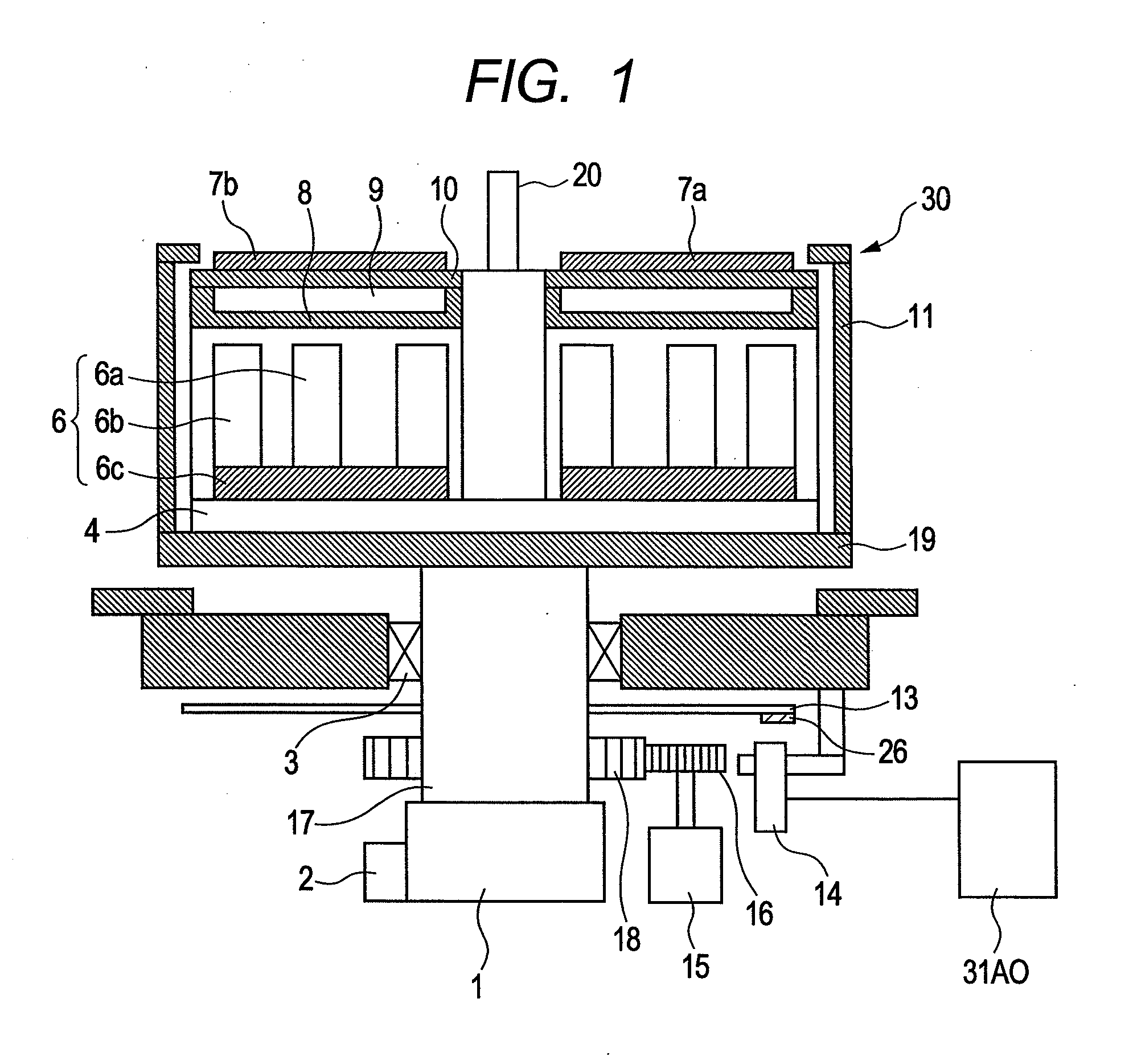
[0119]When the cathode unit was in a positional state shown in Step 1 of FIG. 3, the sensor 14 given in FIG. 1 was positioned at a contact point between the cathode 7b on which the black body part 26 was mounted and the cathode 7a on which no black body part 26 was mounted. The sensor 14 detected the state, and the process controller 31A0 that the discharge of the cathode 7a was initiated. When, from a gas-supply mechanism (not shown), Ar gas was introduced so as to be a pressure of 10 Pa and synchronously a 350 W DC power was applied to the Pd target of the cathode 7a, the discharge was initiated to thereby deposit 10 nm thick Pd film on the substrate.
[0120]Next, when the cathode unit was in a positional state shown in Step 2 of FIG. 3, the sensor 14 was positioned at a portion of mounting the black body part 26 of the cathode 7...
PUM
| Property | Measurement | Unit |
|---|---|---|
| Angle | aaaaa | aaaaa |
Abstract
Description
Claims
Application Information
 - R&D
- Intellectual Property
- Life Sciences
- Materials
- Tech Scout
- Unparalleled Data Quality
- Higher Quality Content
- 60% Fewer Hallucinations
Browse by: Latest US Patents, China's latest patents, Technical Efficacy Thesaurus, Application Domain, Technology Topic, Popular Technical Reports.
© 2025 PatSnap. All rights reserved.Legal|Privacy policy|Modern Slavery Act Transparency Statement|Sitemap|About US| Contact US: help@patsnap.com