
Ratchet hub device

a ratchet hub and ratchet technology, applied in mechanical actuated clutches, bicycles, transportation and packaging, etc., can solve the problems of insufficient structure of the conventional ratchet hub device, failure of the ratchet cylinder to be quickly engaged with the ratchet, etc., to achieve the effect of increasing the quantity of tooth sockets, reducing the depth of each tooth socket, and more smooth riding

Inactive Publication Date: 2011-07-14
HAN VIN ENT
View PDF7 Cites 5 Cited by
  • Summary
  • Abstract
  • Description
  • Claims
  • Application Information

AI Technical Summary

Benefits of technology

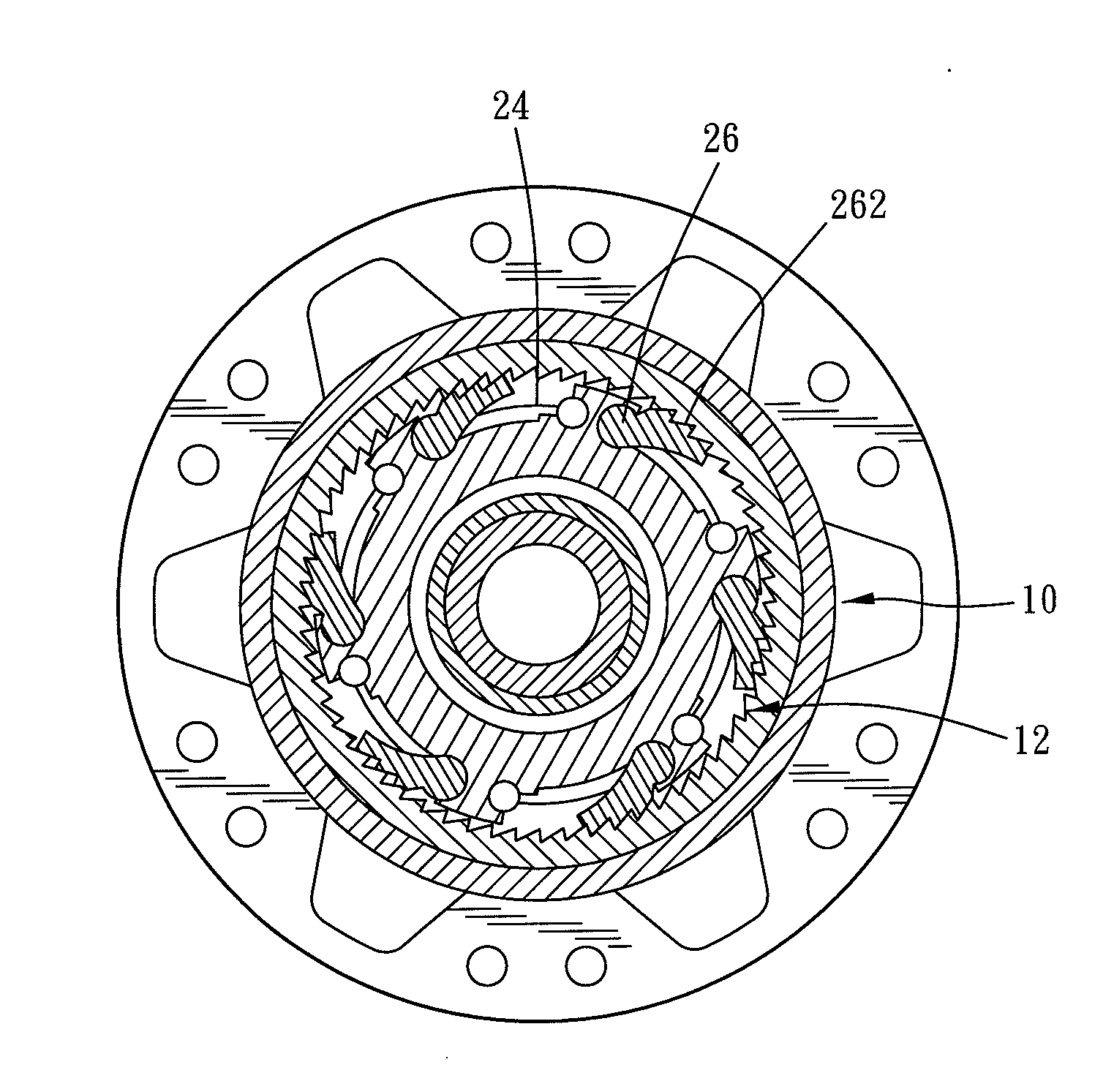
[0007]A conventional ratchet hub device fails to quickly engage with a ratchet cylinder. Further, a structure of the conventional ratchet hub device is not small enough. Therefore, the main object of the present invention is to provide a ratchet hub device which can solve above-mentioned problems of the conventional ratchet hub device. The ratchet hub device of the present invention includes two groups of ratchet members. And there is a half tooth pitch difference between two groups of the ratchet members. Thereby, the ratchet members can quickly engages with tooth sockets of a hub shell, so that a rider can rapidly drive the hub shell to rotate and has a more smooth feeling when riding. The present invention increases a quantity of the tooth sockets so that the depth of each tooth socket can be decreased. Consequently, the hub shell can be made in a smaller structure.
[0010]Thereby, the ratchet hub device of the present invention has the following advantages:
[0011]First, the ratchet hub device has the ratchet members which are divided as a first group and a second group. When a rider pedals a bicycle, the device makes the one group of the ratchet members, which is near the recess, engage with the recess of the hub shell so as to quickly drive the hub shell to rotate and greatly decrease the time from pedaling the bicycle to driving the hub to rotate.
[0012]Second, the ratchet member has more than two pawls, so that a size of the tooth sockets on the recess can be decreased. Consequently, a size of the hub shell can further be decrease as well.

Problems solved by technology

A conventional ratchet hub device fails to quickly engage with a ratchet cylinder.
Further, a structure of the conventional ratchet hub device is not small enough.

Method used


Image

  • Ratchet hub device
  • Ratchet hub device
  • Ratchet hub device

Examples


Embodiment Construction

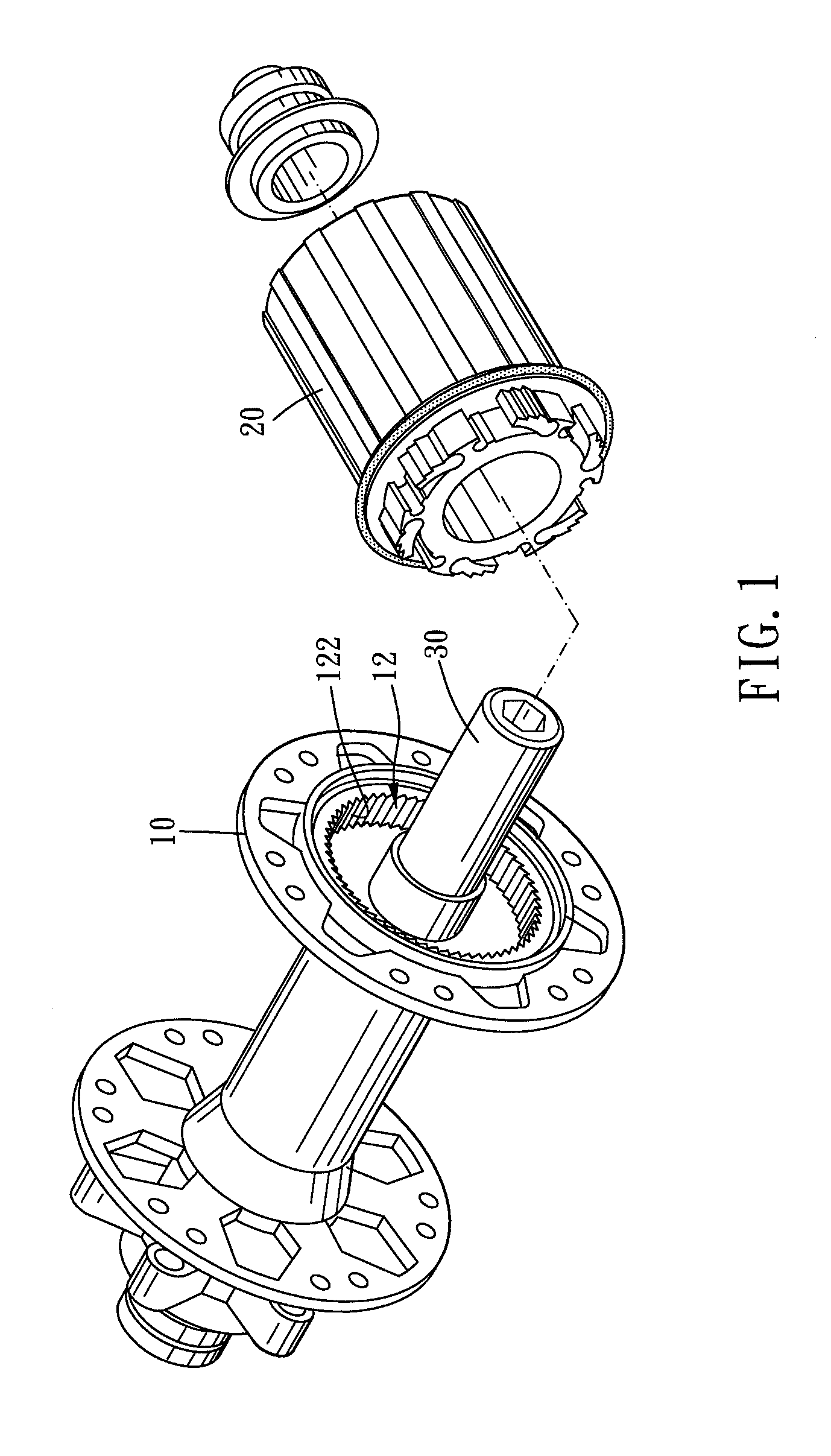
[0019]Please refer to FIG. 1 to FIG. 4. A ratchet hub device of the present invention which is used for a bicycle includes a hub shell (10), a ratchet cylinder (20), and an axle (30). The hub shell (10) is rotatably disposed on the axle (30), and the ratchet cylinder (20), which is rotatably disposed on the axle (30), is combined with the shell hub (10).

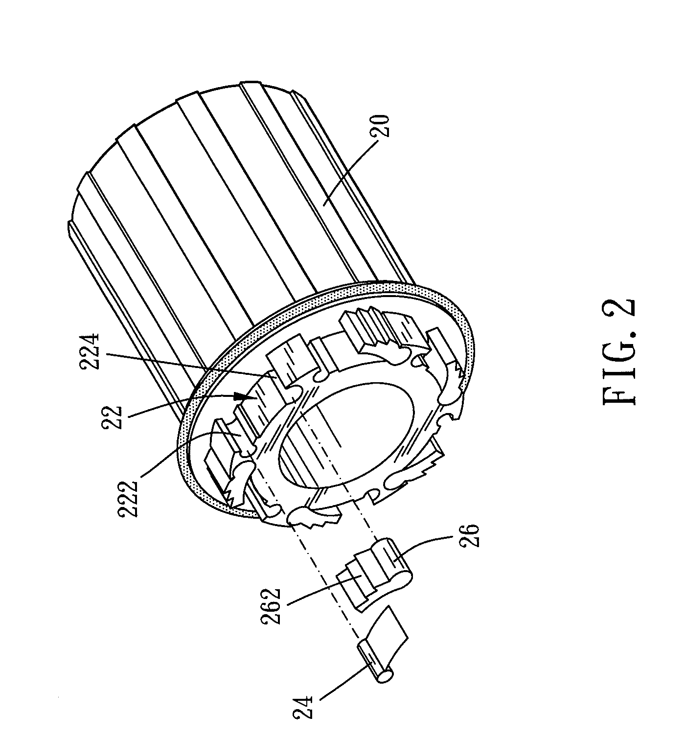
[0020]One end of the hub shell (10) is concavely formed with a recess (12). More than sixty tooth sockets (122) are formed on an inner peripheral surface of the recess (12). The tooth sockets (122) are arranged with an equal interval between each other. Each of the tooth sockets (122) comprises a leading edge (124) and an abutting edge (126), and the interval between two adjacent tooth sockets (122) defines a tooth pitch. As shown in FIG. 2 and FIG. 3, one end of the ratchet cylinder (20), which is toward the hub shell (10), is formed with a wheel like member. The wheel like member is adapted to be received in the recess (12). An out...


PUM


Abstract

A ratchet hub device, which can be quickly meshed to drive a bicycle, includes a hub shell, a ratchet cylinder, and an axle. There are plural tooth sockets and two groups of receiving notches between the hub shell and the ratchet cylinder. The receiving notches of each of the two groups are arranged with an equal interval between each other. Each of the receiving notches of the one group is arranged next to one of the receiving notches of the other group. Two groups of receiving notches receive ratchet members therein and engage with the tooth sockets by turns. Thereby, when a rider re-pedals a bicycle, one group of the ratchet members engage with the near tooth sockets so as to quickly engage with the hub shell and drive the hub shell to rotate.

Description

BACKGROUND OF THE INVENTION[0001]1. Field of the Invention[0002]The present invention relates to a ratchet device for a transmission hub of a bicycle.[0003]2. Description of the Prior Art[0004]A conventional ratchet hub device for a bicycle, as shown in FIG. 5, includes a hub shell (50) and a ratchet cylinder (40) which is engaged with the hub shell (50). The hub shell (50) has a recess (51). The recess (51) has twenty-five tooth sockets (52). Each of the tooth sockets (52) has a leading edge (522) and an abutting edge (524). The abutting edge (524) is almost vertically connected to the leading edge (522). Three ratchet members (42) are disposed on the ratchet cylinder (40) with an equal interval between each other. Each of the ratchet members (42) comprises a pawl (422) to abut against the abutting edge (524) so as to drive the hub shell (50). Said ratchet hub device for a bicycle has the following disadvantages in use:[0005]First, when a rider re-pedals to rotate the ratchet hub d...

Claims


Application Information

Patent Timeline
IPC IPC(8): F16D41/12
CPCB60B27/023F16D41/30B60Y2200/13B60B27/047
Inventor LEE, CHUNG JIA
Owner HAN VIN ENT
Learn More