
System and method for high precision isotope ratio destructive analysis

a destructive analysis and high-precision technology, applied in the field of high-precision isotope ratio destructive analysis, can solve the problems of limiting the analysis timescale, high instrumentation cost, labor cost of highly skilled technicians, etc., and achieves high measurement spatial resolution, fast analysis time, and high precision isotope ratio determination.

Active Publication Date: 2011-07-07
BATTELLE MEMORIAL INST
View PDF3 Cites 12 Cited by
  • Summary
  • Abstract
  • Description
  • Claims
  • Application Information

AI Technical Summary

Benefits of technology

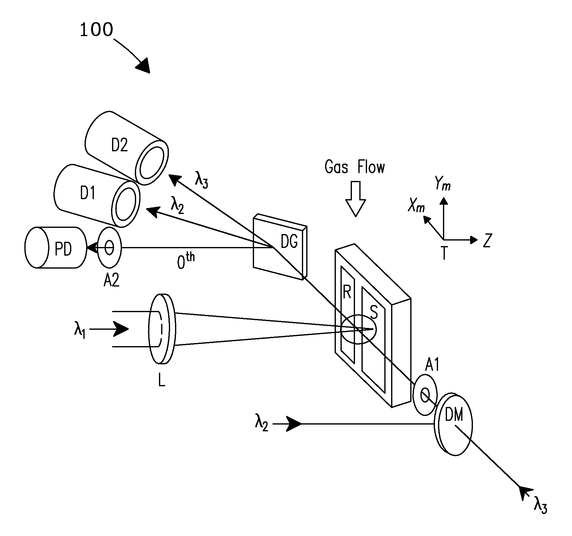
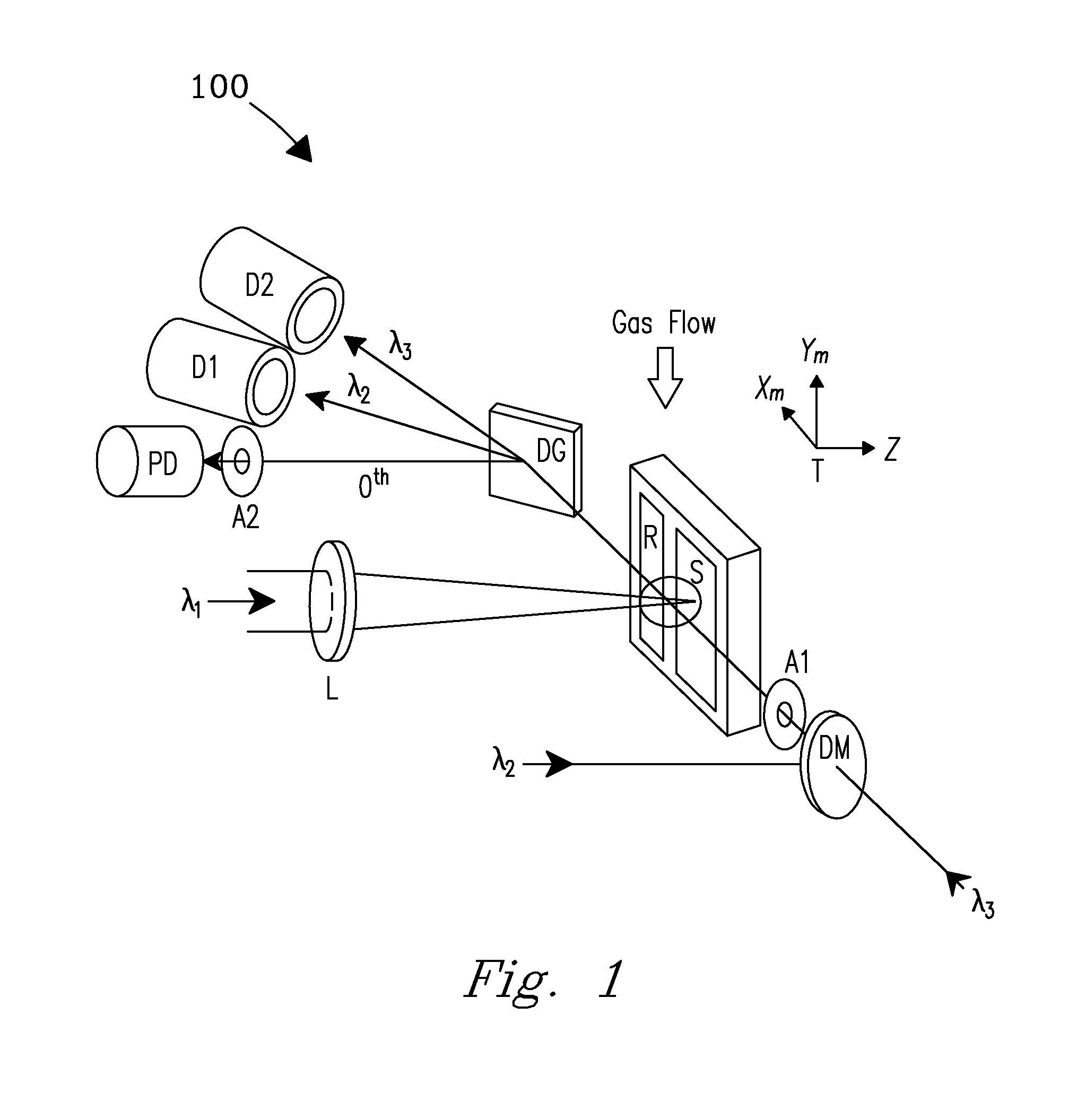
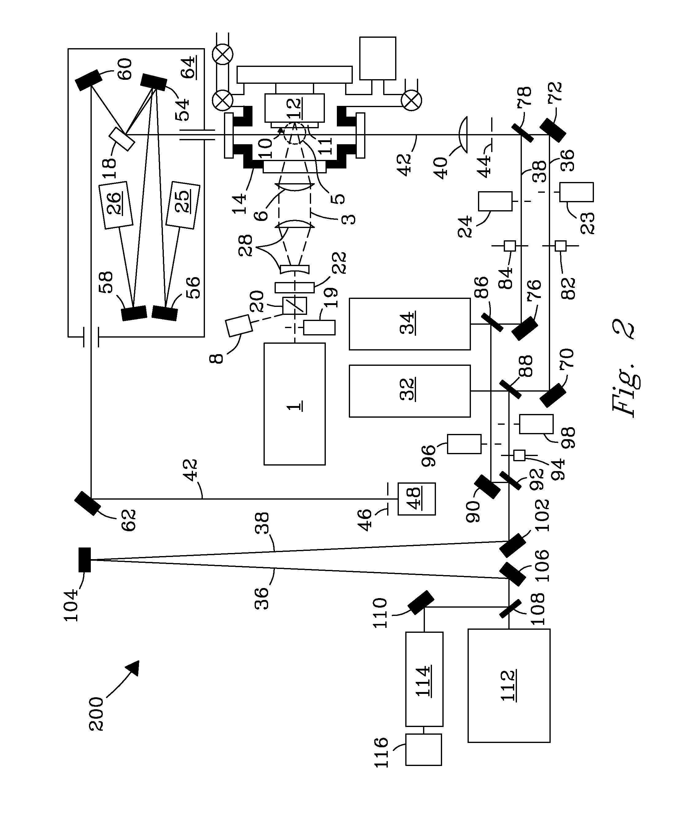
The present invention is a system and method for obtaining high precision isotope ratio determination with fast analysis time. The method involves vaporizing a sample containing at least two isotopes of the same chemical element using a laser ablation pulse and analyzing the resulting vaporization plume using a collinear beam of diode lasers. The isotopic ratios of the absorbed laser beams are determined and compared to the known isotopic composition of the sample. The system can analyze a variety of sample types, including gases, liquids, solids, and particles, and can also collect samples on substrates or from environmental samples. The invention allows for unambiguous determination of the isotopic ratios at approximately 1% or better precision and accuracy, and can also determine the isotopic composition of unknown analytes. The invention is not limited to any particular laser wavelength, pulse energy, or other laser parameters, and can also use a flowing cover gas for laminar flow. The sample can be vaporized in an "as-received" state, meaning it can be vaporized without any prior chemical manipulation or preparation.

Problems solved by technology

While these laboratory measurements are very accurate (±0.1% for low-enriched uranium [LEU] by TIMS, ±0.05% for LEUF6 by GSMS), they are encumbered by the high costs of the instrumentation, supporting facility infrastructure, chain of custody requirements for sample transport from GCEP to the offsite laboratory, and labor costs associated with the highly skilled technicians and scientists who are involved in the sample preparation, instrument operation, maintenance, and data analysis.
The large per-sample expense and analysis timescale restricts DA sampling at a GCEP as a practical matter.
In the case of new, large capacity facilities, this restriction may cast doubt on whether a fully effective DA sampling plan is possible.

Method used


Image

  • System and method for high precision isotope ratio destructive analysis
  • System and method for high precision isotope ratio destructive analysis
  • System and method for high precision isotope ratio destructive analysis

Examples


Embodiment Construction

[0029]A system and process are disclosed that provide high precision isotope ratio determination at high measurement spatial resolution and fast analysis time for destructive analyses for isotope ratio determination of relative isotope abundance distributions in collected gases, liquids, solids, and particulate samples. As used herein, the term “destructive analysis” (DA) means an analysis which consumes sample material and / or changes sample morphology and where the sample being measured is not returned to the batch it was taken from. The term encompasses analyses of bulk samples including, e.g., uniform liquids or solids where repeat analyses may be performed with replicate aliquots. In addition, analyses of non-uniform samples (e.g., atmospheric particulate collections) generically referred to as “Environmental Samples” (ES) herein can also be performed.

[0030]The term “high spatial resolution” as used herein refers to the ability to resolve individual particles in various complex ...


PUM


Abstract

A system and process are disclosed that provide high accuracy and high precision destructive analysis measurements for isotope ratio determination of relative isotope abundance distributions in liquids, solids, and particulate samples. The invention utilizes a collinear probe beam to interrogate a laser ablated plume. This invention provides enhanced single-shot detection sensitivity approaching the femtogram range, and isotope ratios that can be determined at approximately 1% or better precision and accuracy (relative standard deviation).

Description

CROSS REFERENCE TO RELATED APPLICATION[0001]This application claims priority from U.S. patent application Ser. No. 12 / 831,985 filed Jul. 7, 2010 which claimed priority from provisional patent application No. 61 / 223,795 filed 8 Jul. 2009. The contents of each of these two applications are hereby incorporated in their entirety.STATEMENT REGARDING RIGHTS TO INVENTION MADE UNDER FEDERALLY-SPONSORED RESEARCH AND DEVELOPMENT[0002]This invention was made with Government support under Contract DE-AC05-76RLO1830 awarded by the U.S. Department of Energy. The Government has certain rights in the invention.FIELD OF THE INVENTION[0003]The present invention relates generally to the determination of relative amounts of two isotopes. More particularly, the invention relates to a system and method for quickly and accurately detecting and analyzing relative isotope abundance distributions in desublimated gases, gases chemisorbed into solid complexes, dried liquids, solids, and particulate samples, an...

Claims


Application Information

Patent Timeline
Patent Type & Authority Applications(United States)
IPC IPC(8): G01J3/30
CPCG01J3/427G01N21/3103G01N2033/0093G01N21/631G01N2021/1761G01N21/3151G01N33/0093
Inventor BUSHAW, BRUCE A.ANHEIER, JR., NORMAN C.PHILLIPS, JON R.
Owner BATTELLE MEMORIAL INST
Learn More