Method for making electrical windings for electrical apparatus and transformers and windings obtained by said method

a technology of transformers and windings, which is applied in the direction of transformers/inductances, resistors, and magnetic cores of electric motors. it can solve the problems of poor thermal contact between the winding and the holder, the winding cannot conform to abrupt variations in the winding direction, and the winding is oversized, so as to improve the insulation efficiency and cost efficiency. , the effect of large-scale production

Active Publication Date: 2011-07-07
PULNIKOV SERGEY
View PDF8 Cites 11 Cited by
  • Summary
  • Abstract
  • Description
  • Claims
  • Application Information

AI Technical Summary

Benefits of technology

[0013]Another object of the present invention is to utilize a simple construction of the mandrel defining the internal shape of the winding.
[0022]As described further the presented manufacturing method reduces a number of conventional manufacturing steps. Besides, this method allows the use of advanced materials and automation of the process.

Problems solved by technology

Oversizing these holders affects the size of the windings as well as the size of the whole device.
Copper wire cannot conform to abrupt variations in the winding direction.
This leads to a poor thermal contact between the winding and the holder.
In order to avoid overheating and insulation failure, the current density in the winding has to be reduced accordingly, which further increases space occupied by the winding.
Besides, polymer compounds used for impregnation of electric windings shrink during curing.
So for a majority of practical cases such an approach seems unsuitable.
A disadvantage of such an approach is in the need of assembly and disassembly of a fairly complex mandrel, which would impede automation of such a process.
However it also increases viscosity of the compound, which increases the chance for porosity.
Besides, the proposed insulating material does not have the highest electrical strength, therefore such transformers are not applied for voltages above 35 kV.
Practice of exploitation of such dry transformers with cast windings shows that due to mechanical forces at short circuits and vibrations cracks can emerge in cast insulation.
With regard to conventional technology, in large windings there is a problem of achieving sufficient mechanical rigidity and cooling.
This forces transformer producers to use expensive helical and continuous disk type of windings instead of more technological layer windings.

Method used


Image

  • Method for making electrical windings for electrical apparatus and transformers and windings obtained by said method
  • Method for making electrical windings for electrical apparatus and transformers and windings obtained by said method
  • Method for making electrical windings for electrical apparatus and transformers and windings obtained by said method

Examples


Embodiment Construction

[0075]The proposed invention is related to the wide range of windings suited for low power transformers and inductors, medium power devices as well as for high voltage and high power devices.

[0076]There are specific requirements for each power range and each voltage range. In order to meet these requirements each step in the technology presented further has to be adopted accordingly.

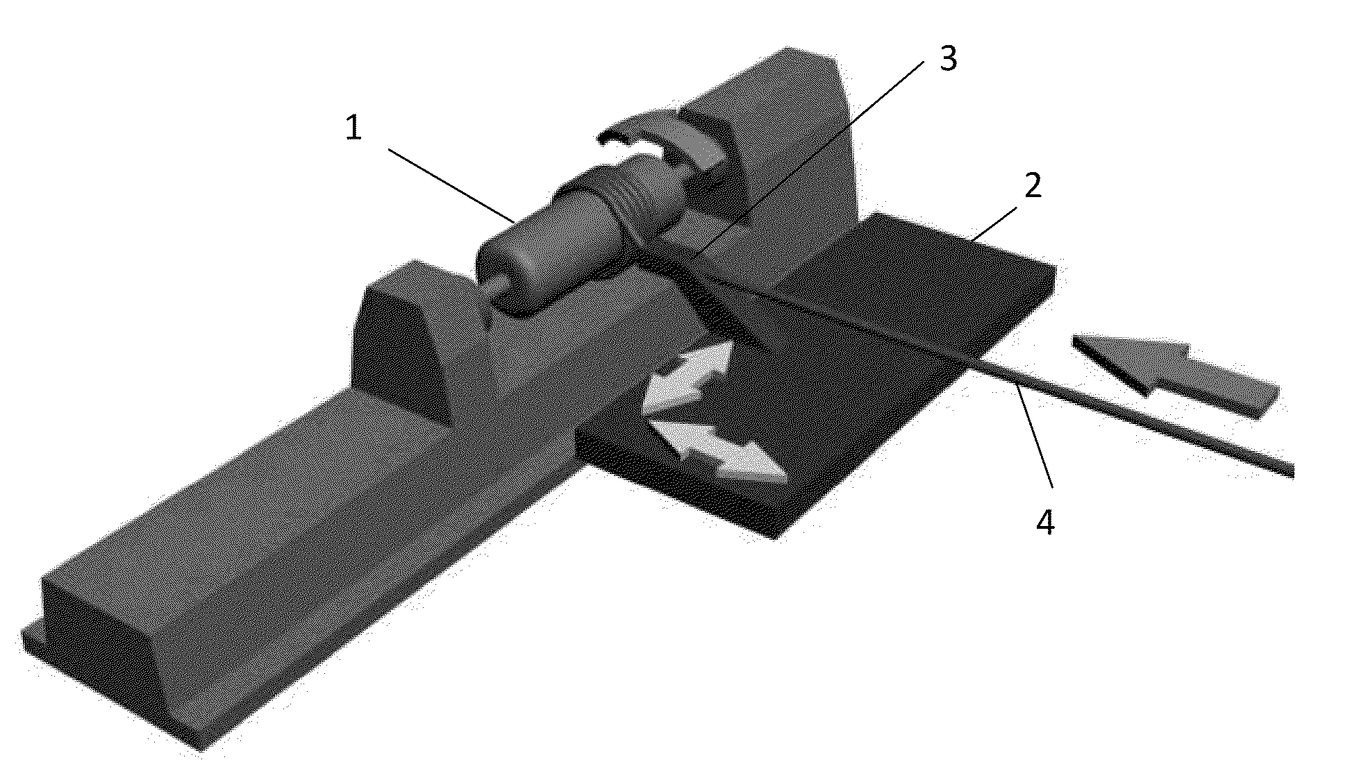
[0077]Some basics of the winding process are illustrated in FIG. 1. The mandrel 1 defining the internal shape of the winding is fixed in a turning machine. Next to the turning machine there is a moving table 2 that can execute translational movements along the mandrel and also towards the mandrel and away from the mandrel as indicated by arrows. There is a winding eye 3 installed on the moving table 2 that guides winding material 4. The winding eye can contain a guiding profile corresponding to the profile of the winding material. This guiding profile can be covered with a low friction material like Tefl...


PUM

PropertyMeasurementUnit
winding angleaaaaaaaaaa
voltagesaaaaaaaaaa

Abstract

This invention relates to a method of manufacturing electrical windings for electrical apparatus and transformers. This method comprises the following steps: manufacturing a metal mandrel defining the internal shape of the winding; installation of an internal insulation and support; installation of side rings; pouring impregnation compound on horizontally turning mandrel for obtaining a thin layer on the operational area of the mandrel and side surface of the side rings; optionally curing this layer; fixation of the first end wire using one of side rings; manufacturing winding with simultaneous pouring of compound onto the mandrel; possibly introducing intermediate insulation and / or reinforcing layers of preimpregnated reinforced plastics; optionally inserting premade sleeves around section of the winding; fixation of the second end wire using one of side rings; possibly introducing external insulation or reinforcing layers of preimpregnated reinforced plastics; possibly manufacturing secondary windings on top of the wound winding; curing the winding; extraction of the cured winding or a set of cured windings from the mandrel.The invention also relates to winding structures obtained by this method.

Description

CROSS-REFERENCE TO RELATED APPLICATIONS[0001]This application is continuation of application Ser. No. 12 / 144,855 filed Jun. 24, 2008 now abandoned.TECHNICAL FIELD[0002]This invention is related to the production of electrical windings for electrical apparatus and transformers. This invention is also related to winding structures obtained by the said method.BACKGROUND INFORMATION[0003]This invention relates to a method of manufacturing electrical windings for electrical apparatus and transformers. This method comprises the following steps: manufacturing a metal mandrel defining the internal shape of the winding; installation of an internal insulation and support; installation of side rings; pouring impregnation compound on horizontally turning mandrel for obtaining a thin layer on the operational area of the mandrel and side surface of the side rings; optionally curing this layer; fixation of the first end wire using one of side rings; manufacturing winding with simultaneous pouring ...

Claims


Application Information

Patent Timeline
Patent Type & Authority Applications(United States)
IPC IPC(8): H01F27/32H01F41/06
CPCH01F27/322H01F27/324H01F41/0633Y10T29/4902H01F41/127Y10T29/49071Y10T29/49073H01F41/0687H01F41/082H01F41/098
Inventor PULNIKOV, SERGEY
Owner PULNIKOV SERGEY
Why Eureka
Try Eureka