
Vehicle-used composite braking/accelerating system

Inactive Publication Date: 2011-07-07
CHEN TIEN LI +1
View PDF3 Cites 14 Cited by
  • Summary
  • Abstract
  • Description
  • Claims
  • Application Information

AI Technical Summary

Benefits of technology

[0008]A primary objective of the present invention is to provide a vehicle-used composite braking / accelerating system. The composite braking / accelerating system includes a smart electronic transmission control (ETC) system, and a movable motor, and is adapted for recycling the kinetic energy of the moving vehicle when the vehicle is braked to decelerate, in that the recycled kinetic energy is transformed into electrical energy and saved into a battery. When the battery contains sufficient electrical energy saved therein, the composite braking / accelerating system allows the battery to output the electrical energy for driving the vehicle to move, so as to save the fuel consumption. When the electrical energy saved in the battery is insufficient, the engine of the vehicle operates to drive the vehicle and may even charge the battery. When the vehicle is solely driven by the engine, an actuator disengages the movable motor from the tire system, so as to completely exert the capacity of the engine and eliminate the restraint of the movable motor.
[0009]For achieving the objective of the present invention, a vehicle-used composite braking / accelerating system is provided. In accordance with the composite braking / accelerating system, a movable motor is provided adjacent to a wheel of the vehicle. The movable motor is electrically connected to a control circuit and a battery. When the vehicle is moving and the moving vehicle is braked to decelerate, in which the driver of the vehicle slightly steps on the braking device, the control circuit instructs the movable motor to execute a generator function and drives the actuator to operate. The movable motor includes a coil member and a magnetic member. The magnetic member includes a permanent magnet. When the coil member and the magnetic member are correspondingly positioned and relatively rotated, the movable motor generates electrical energy, and saves the generated electrical energy into the battery. In such a way, the kinetic energy of the moving vehicle is transformed into electrical energy for saving the fuel consumption.
[0010]When the driver of the vehicle applies a stronger force stepping on the braking device, the braking system of the vehicle is enabled to further decelerate the moving vehicle. Accordingly, the composite braking / decelerating system is adapted for facilitating to accelerate the vehicle when vehicle is driven to move forward. When the electrical energy saved in the battery is sufficient and the tire rotation speed is lower than a predetermined value, the control circuit instructs the movable motor to execute a motor-output-power function, in which the battery outputs the electrical energy to the coil member and the actuator is instructed to operate, so that the coil member and the magnetic member are effectively and relatively rotated to drive the wheel to rotate.
[0012]Furthermore, when the vehicle is driven in a rainy weather or a slippery road, the control circuit is also adapted for monitoring the rotation speed of each tire for adjusting the output of each motor so as to avoid the tire slippage.

Problems solved by technology

When the electrical energy saved in the battery is insufficient, the engine of the vehicle operates to drive the vehicle and may even charge the battery.

Method used


Image

  • Vehicle-used composite braking/accelerating system
  • Vehicle-used composite braking/accelerating system
  • Vehicle-used composite braking/accelerating system

Examples


first embodiment

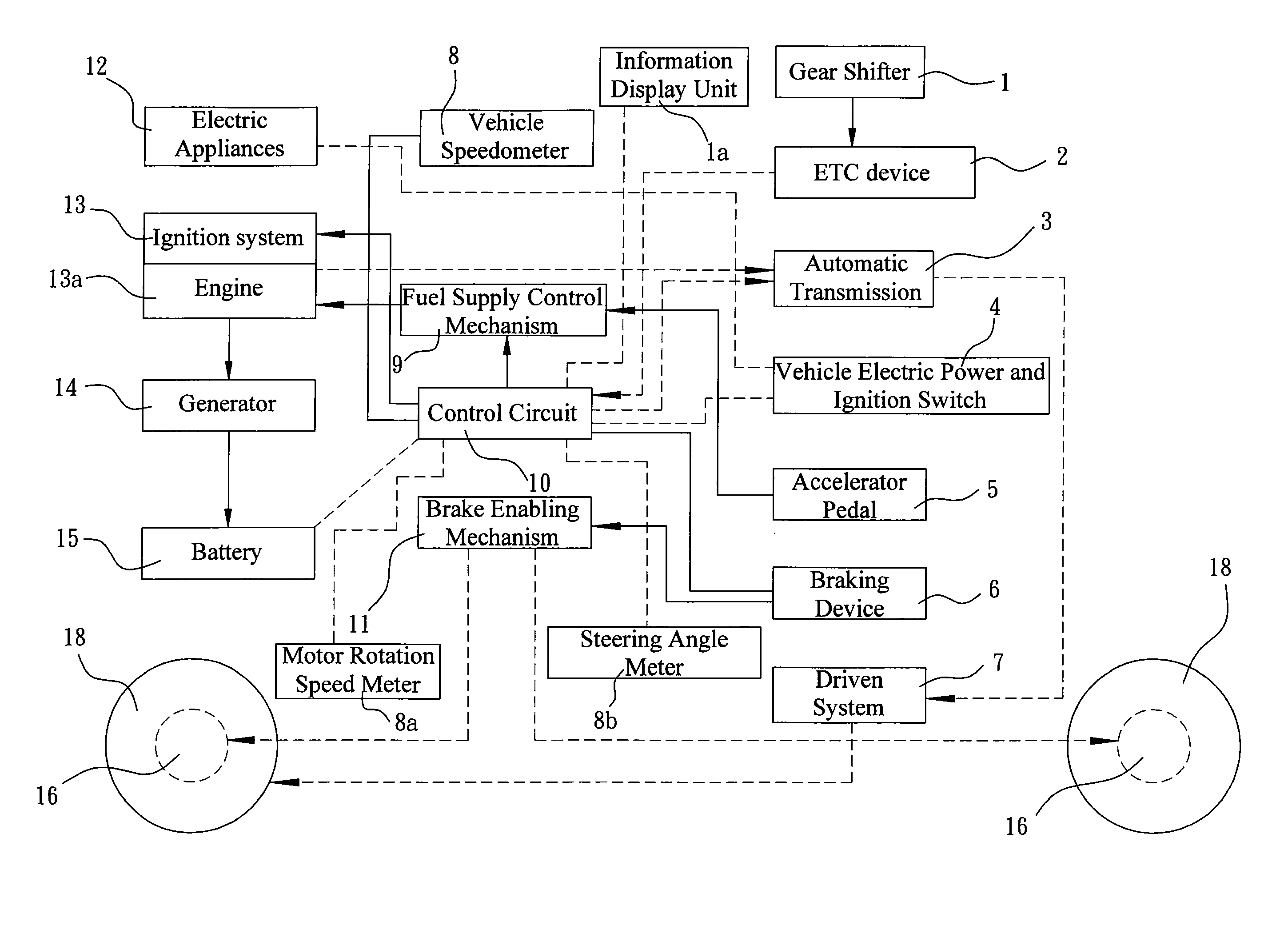
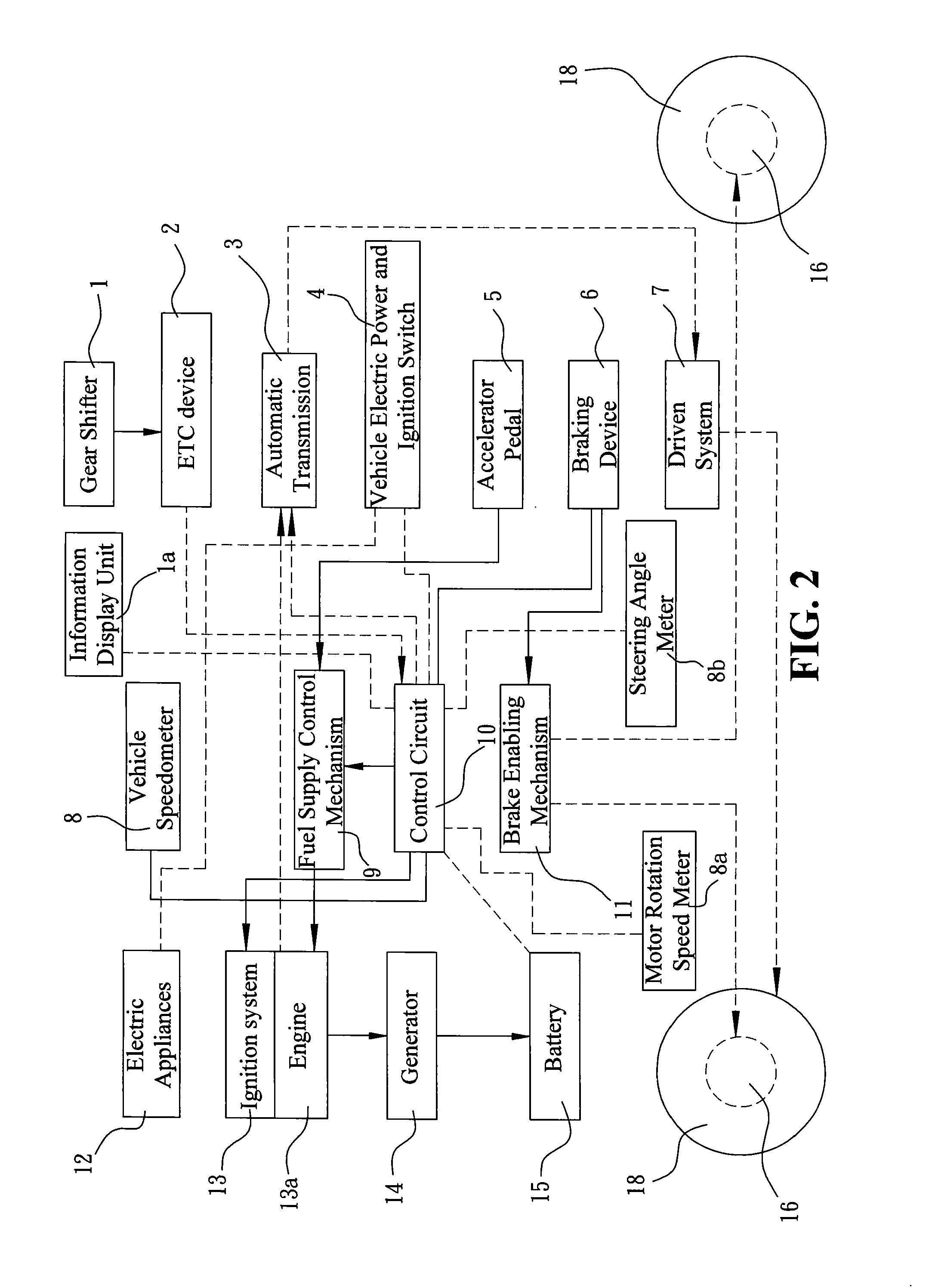
[0024]FIG. 2 is a schematic diagram illustrating an embodiment of the present invention. Referring to FIG. 2, there is shown a vehicle-used composite braking / accelerating system. The composite braking / accelerating system is adapted for a vehicle including an additional smart electronic transmission control (ETC) system. The smart ETC system includes an engine 13a, an ignition system 13 of the engine 13a, a generator 14, a control circuit 10, a vehicle speedometer 8, a battery 15, a fuel supply control mechanism 9, a gear shifter 1, an ETC device 2, an automatic transmission 3, a vehicle electric power and ignition switch 4, an accelerator pedal 5, a braking device 6, and a driven system 7. The control circuit 10 is electrically connected to the battery 15, the vehicle speedometer 8, the ignition system 13, the ETC device 2, the automatic transmission 3, the vehicle electric power and ignition switch 4, and the braking device 6 which is adapted for enabling a brake enabling mechanism...

third embodiment

[0031]FIG. 7 illustrates the present invention, in which the coil member and the magnetic member are restricted from rotation relative to each other. FIG. 8 illustrates the embodiment as shown in FIG. 7, while the coil member and the magnetic member are allowed to rotate relative to each other. As shown in FIGS. 7 and 8, the rotation member 17e is secured to the fixing member 17d, and the coil member 17c and the magnetic member 17b are disposed at corresponding positions of the fixing member 17d and the rotation 17e respectively. The actuator 17a is disposed on the rotation mechanism 17e, and thus the actuator 17a is allowed to rotate together with the rotation mechanism 17e. Referring to FIG. 7, when the control circuit 10 turns off the actuator 17a so as to control the actuator not to operate, the actuator 17a remains apart from the axle 182 which is rotation together with the rim 181, and thus there is no effective relative rotation can be generated between the coil member 17c an...


PUM


Abstract

A vehicle-used composite braking / accelerating system is provided. In accordance with the composite braking / accelerating system, a movable motor is provided adjacent to a wheel of the vehicle. The movable motor is electrically connected to a control circuit and a battery. When the vehicle is moving and the moving vehicle is braked to decelerate, in which the driver of the vehicle slightly steps on the braking device, the control circuit instructs the movable motor to execute a generator function and drives the actuator to operate. The movable motor includes a coil member and a magnetic member. When the coil member and the magnetic member are correspondingly positioned and relatively rotated, the movable motor generates electrical energy, and saves the generated electrical energy into the battery. In such a way, the kinetic energy of the moving vehicle is transformed into electrical energy for saving the fuel consumption.

Description

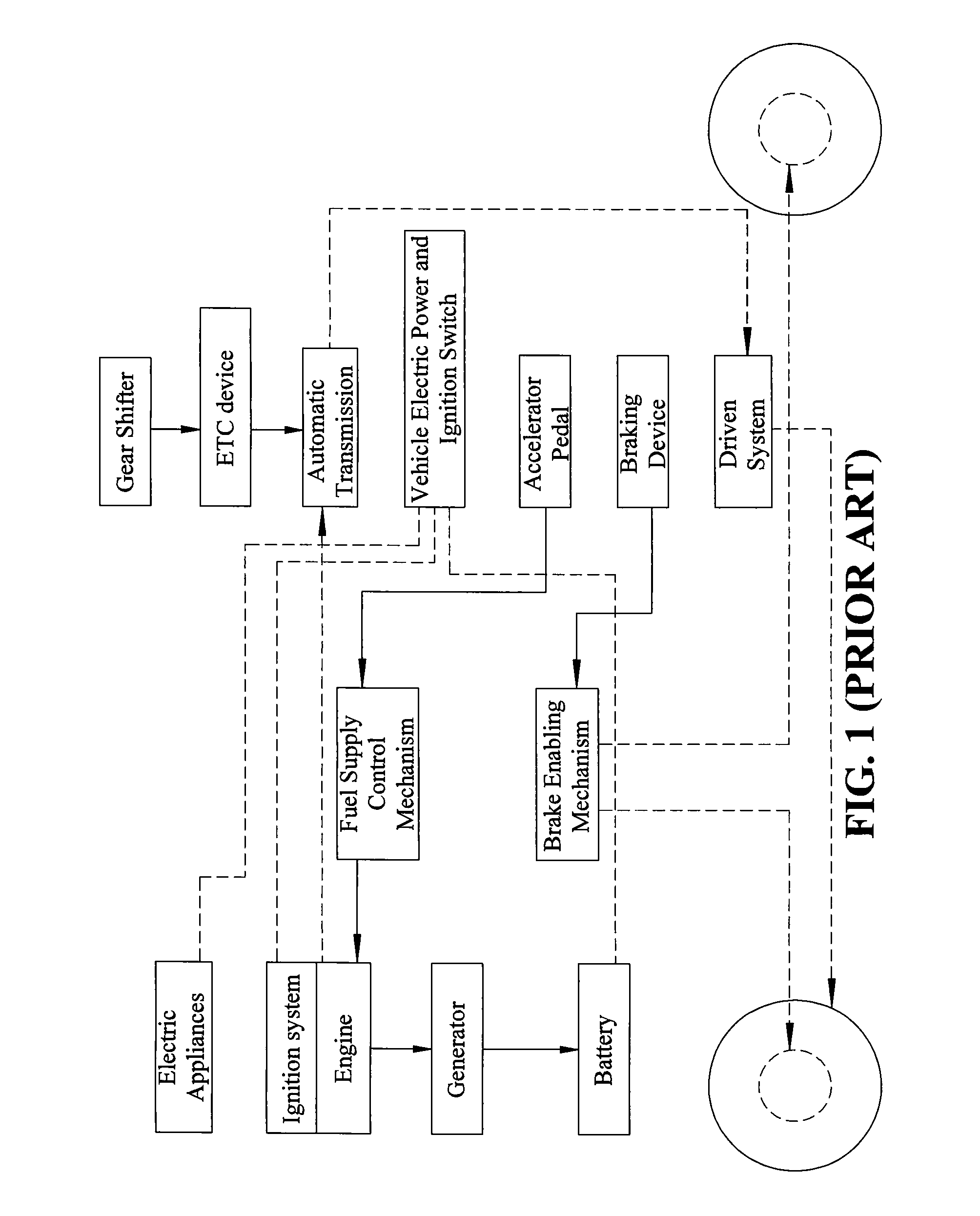
BACKGROUND OF THE INVENTION[0001]1. Field of the Invention[0002]The present invention relates generally to a vehicle-used composite braking / accelerating system. When a vehicle is braked to decelerate, the composite braking / accelerating system is used for transforming the kinetic energy of the moving vehicle into electrical energy and saving the electrical energy in a battery. When the vehicle is being driven to move forward or accelerate, the electrical energy saved in the battery can be outputted from the battery for facilitating to accelerating the vehicle, so as to save fuel consumption.[0003]2. The Prior Arts[0004]Recently, the automobile enterprises are fast developed. Driving a car usually helps to save the time spent on transportation. However, it also adversely consumes fuel and produces carbon dioxide, which is a main factor causing the green house effect and destroying the quality of the air. Typically, only 30% of fuel burned out by a vehicle engine is used for generating...

Claims


Application Information

Patent Timeline
IPC IPC(8): B60W20/00
CPCB60W10/08B60W10/11B60W20/00Y02T10/6217B60L11/123Y02T10/7077Y02T10/7005B60W30/18127B60L50/61Y02T10/62Y02T10/70B60W20/13Y02T10/7072
Inventor CHEN, TIEN-LICHANG, TEN-LEE
Owner CHEN TIEN LI
Learn More