
Plasmon head with hydrostatic gas bearing for near field photolithography

a technology of hydrostatic gas bearings and plasmon heads, which is applied in the field of plasmonic heads with hydrostatic gas bearings, can solve the problems of increasing the difficulty and complexity of using the established method of optical projection lithography at the short optical wavelength, the use of wavelengths in the deep ultraviolet, the extreme ultraviolet (euv), or the x-ray regime requires increasingly difficult adjustments of the lithographic process, and the final resolution of conventional photolithography is restricted by the diffraction

Inactive Publication Date: 2011-06-30
FIRST PRINCIPALS
View PDF28 Cites 7 Cited by
  • Summary
  • Abstract
  • Description
  • Claims
  • Application Information

AI Technical Summary

Benefits of technology

This approach provides low-cost, high-throughput, maskless nanophotolithography with minimized vibration errors, capable of creating features smaller than 100 nm, suitable for desktop applications and complex structures like MEMS, while reducing the need for expensive mask changes.

Problems solved by technology

The ultimate resolution of conventional photolithography is restricted by the diffraction limit.
It is becoming increasingly difficult and complex to use the established method of optical projection lithography at the short optical wavelengths required to reach the desired feature sizes.
For example, the use of wavelengths in the deep ultraviolet, the extreme ultraviolet (EUV), or the X-ray regime requires increasingly difficult adjustments of the lithographic process, including the development of new light sources, photo-resists, and optics.
Creating the photo-mask, however, is time intensive, expensive, and does not easily permit design changes.
Maskless nanolithography, including electron-beam and scanning-probe lithography, offers the desired flexibility, but is limited by low throughput and extremely high cost.
The spinning master disk, however, is subject to vibration and spindle run-out errors that lead to patterning errors and potential collisions between the slider and the photo-resist.
If the plasmonic lens contacts the master disk it can be coated with photo-resist, potentially smearing the lens and causing patterning errors.
Finally, a spinning master disk is not a practical method of making more complex structures, such as for example micro electrical mechanical systems (MEMS).

Method used


Image

  • Plasmon head with hydrostatic gas bearing for near field photolithography
  • Plasmon head with hydrostatic gas bearing for near field photolithography
  • Plasmon head with hydrostatic gas bearing for near field photolithography

Examples


Embodiment Construction

[0033]The entire content of U.S. Provisional Patent Application Ser. No. 61 / 172,685, filed Apr. 24, 2009, is hereby incorporated by reference.

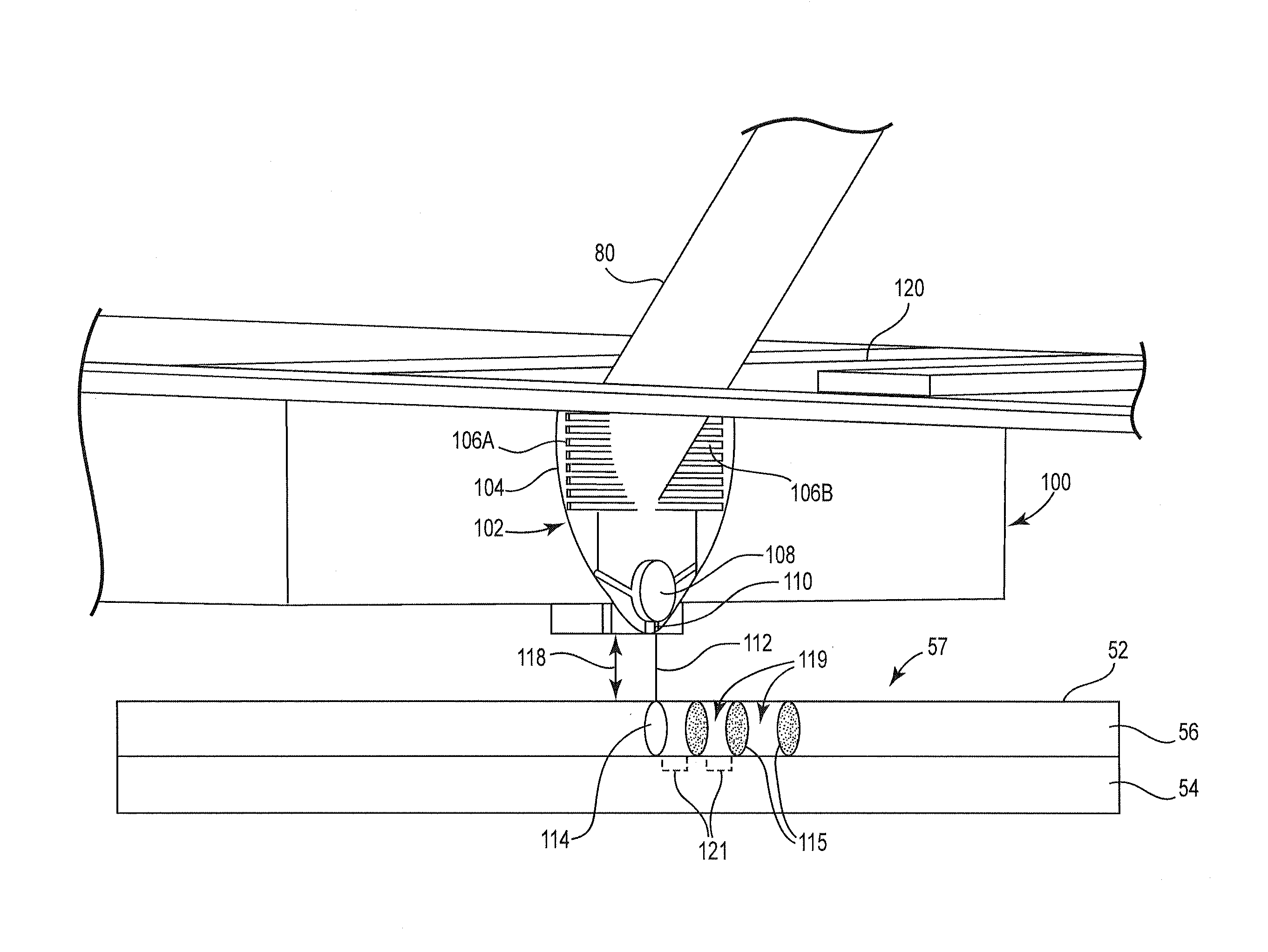
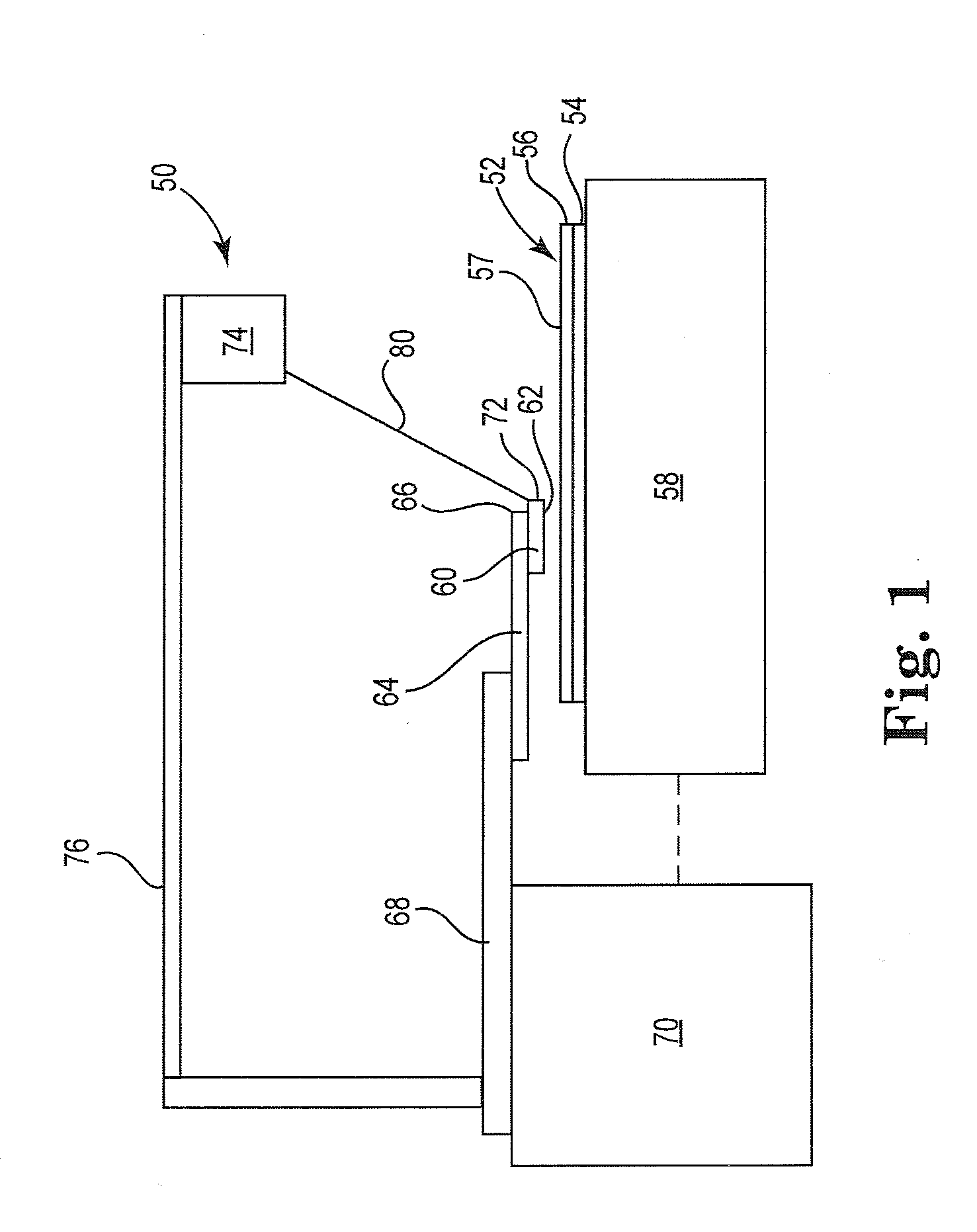
[0034]FIG. 1 is a schematic illustration of the system 50 for maskless, nano-scale, photolithography in accordance with an embodiment of the present invention. A master 52 including a substrate 54 with photo-resist layer 56 supported on X-Y stage 58. Slider 60 has an air-bearing surface (ABS) 62 that is oriented toward the master 52.

[0035]The slider 60 is mounted on a suspension 64 similar to a conventional suspension like that used in magnetic recording disk drives, with a head gimbal assembly or flexure 66 that permits the slider 60 to “pitch” and “roll” relative to the master 52. The suspension 64 is connected to support arm 68 that is supported by controller 70. The support aim 68 applies a preload to the suspension 64 to maintain the flying ability of the slider 60.

[0036]In one embodiment, the support arm 68 is fixedly mounted on controll...


PUM

PropertyMeasurementUnit
fly heightaaaaaaaaaa
wavelengthaaaaaaaaaa
frequenciesaaaaaaaaaa

Abstract

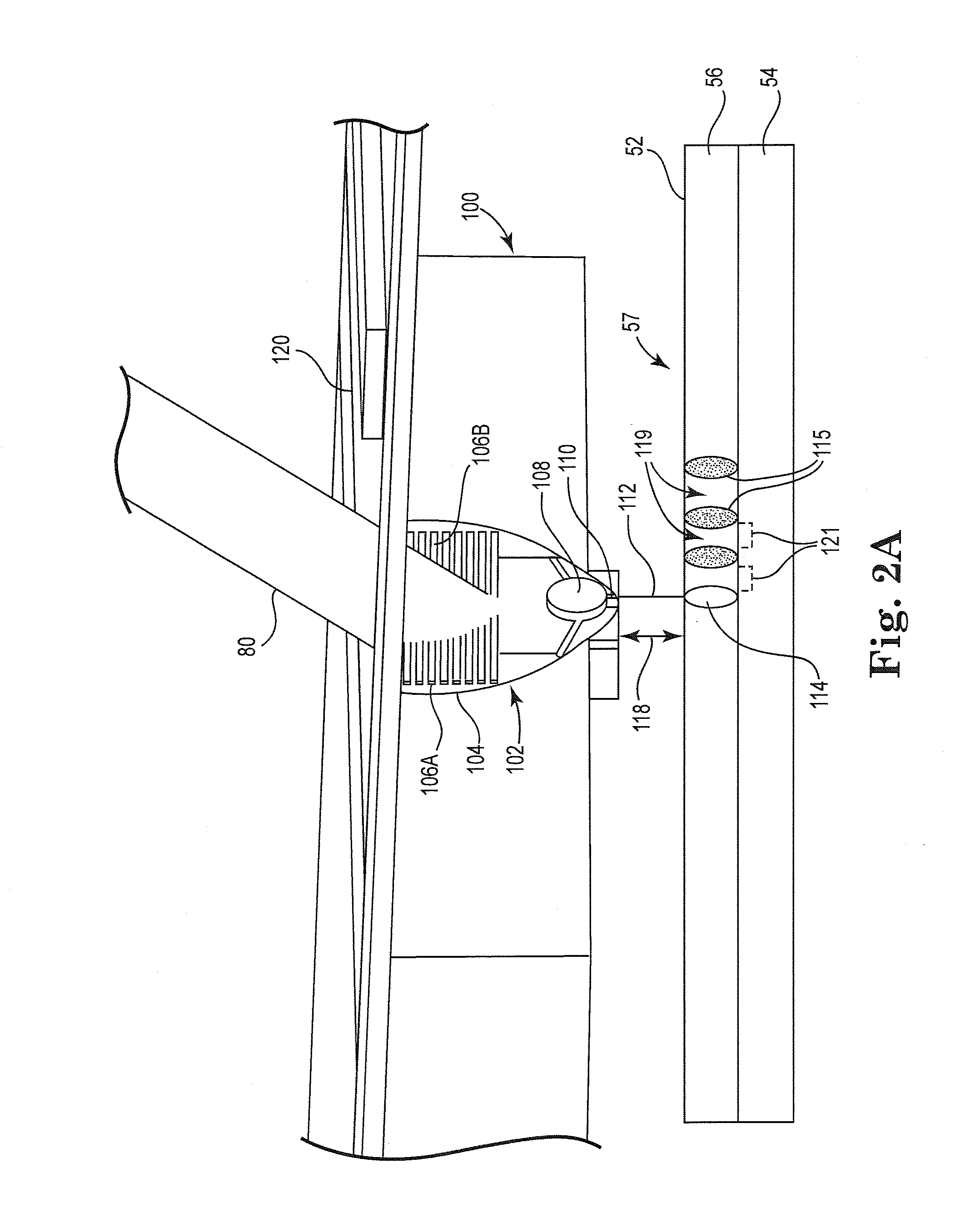
A low-cost approach to near field nano-scale photolithography using a plasmonic head with hydrostatic gas bearings. The hydrostatic gas bearing flies the plasmonic head at less than 100 nm, and more preferably less than 50 nm, above the photo-resist without the need to spin the substrate. The plasmonic head concentrates short-wavelength surface plasmons into about sub-100 nm regions on the photo-resist and can pattern features of about 80 nm or less.

Description

RELATED APPLICATIONS[0001]The present application claims the benefit of U.S. Provisional Patent Application Ser. No. 61 / 172,685 entitled Plasmon Head with Hydrostatic Gas Bearing for Near Field Photolithography, filed Apr. 24, 2009.FIELD OF THE INVENTION[0002]This invention relates to plasmonic heads with hydrostatic gas bearings for near field nano-scale photolithography.BACKGROUND OF THE INVENTION[0003]The continuing size reduction of integrated circuits to nanometer (nm) scale dimensions requires the development of new lithographic techniques. The ultimate resolution of conventional photolithography is restricted by the diffraction limit. It is becoming increasingly difficult and complex to use the established method of optical projection lithography at the short optical wavelengths required to reach the desired feature sizes. For example, the use of wavelengths in the deep ultraviolet, the extreme ultraviolet (EUV), or the X-ray regime requires increasingly difficult adjustments...

Claims


Application Information

Patent Timeline
Patent Type & Authority Applications(United States)
IPC IPC(8): G03F7/20G03B27/42G11B11/03
CPCB82Y10/00G11B5/743G11B2005/0021G11B5/865G11B5/855
Inventor BOUTAGHOU, ZINE-EDDINE
Owner FIRST PRINCIPALS
Learn More